
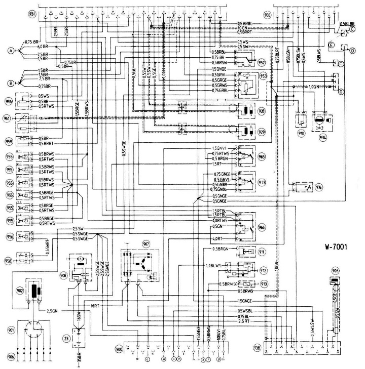
23 Battery
900 Engine connector
and Airbag
b Electric fuel pump
with Maintenance Intervals
d Dynamic oil level measurement
f Remote transmission of measured temperature value
g Static oil level measurement
901 Ignition distributor
902 Ignition coil
903 Position sensor
906 Spark plugs
907 Alternator
908 Starter
910 Temperature switch, 45°C
911 Oil pressure switch
912 Oil level sensor
913 Temperature gauge sensor
928 Speed sensor
929 Reference mark sensor (synchronization)
931 DME control unit (in the glove compartment)
933 Electronic idle speed control
934 Actuator
938 Diagnostic connector
952 Throttle switch
953 Air flow meter
955 Nozzle
956 Cold Start Injector
958 Thermal time switch
973 Relay 2 (relay board)
976 Temperature switch, 0°C
986 Pressure sensor
A Mass of the final stage
In Mass of electronic circuit
With Automatic Transmission Connection
D Connecting terminal 15
E With a manual transmission connected
F Air Conditioner
G Vehicle Wiring Harness