
Electrical diagrams are necessary when troubleshooting electrical equipment and when installing additional equipment; the diagrams show the signal path and cable routing. The corresponding current circuit must be closed, otherwise no electric current will flow through this circuit. For example, it is not enough to supply only positive voltage to the headlights without simultaneously connecting them to ground.
Therefore, the ground wire from the battery is connected to the body. However, this connection to the ground is often insufficient, and the corresponding consumer is connected to the ground directly by a ground wire, the insulation of which is usually brown. Relays, switches, fuses, measuring elements, electrically, motors and other electrical elements are included in individual current circuits. For correct connection, these elements have markings on their contacts.
To organize the interlacing of wires in electrical diagrams, individual current circuits are arranged vertically and numbered.
The vertical lines at the top connect to the thick black line, which represents the current busbar in the distribution box, and therefore the connection of the current circuits to the positive power supply. At the bottom, the vertical lines connect to the horizontal line, which represents the connections to ground. The connection to ground is usually made by connecting the unit housing to the body, but in some cases the ground can be supplied via a separate wire from the ground point on the body.
If a square with a number is depicted in a break in a current circuit, the number corresponds to the number of the current circuit into which this current circuit passes.
The best way to use electrical diagrams is as follows:
First, the corresponding element of the circuit is found from the list of symbols, for example, a fan switch. In the right column next to the name of the element, the corresponding current circuit is indicated with its number, which is also indicated on the electrical diagram at the bottom on the horizontal line.
To read an electrical diagram, you need to know the designations of some elements, in addition, you should know the most important symbols of electrical diagrams.
Relays and control units are usually marked with the letter K. The lines inside represent the internal connections. They show how the relays and other electrical and/or electronic components are connected to each other and to the relay board.
The contact designations are located directly next to the relay.
The terminal designations are standardized according to DIN. The most important terminal designations are as follows.
Terminal 15 is recorded through the ignition switch. Voltage is present on the terminal only after the ignition is turned on. The wires are usually green or green with colored stripes.
Terminal 30. Battery voltage is always present on this terminal. The wires are usually red or red with colored stripes.
Terminal 31 connected to ground. Ground wires are mostly brown. Each wire on the electrical diagram has a digital and alphanumeric designation.
Example: 2.5 GNR.T
The numbers indicate the cross-section of the wire in mm². The letters indicate the color of the wire. If the designation consists of two groups of letters, as in this example, the first letter sequence indicates the main color of the wire (GN - green) and the second (RT - red) - the additional color. Since it happens that wires of the same color are used in different current circuits, it is recommended to check the color combinations of the wires connected to the connection terminals.
Wires that are connected to each other via individual or multi-pin connectors have a digital combination in addition to the connector designation letter.
All elements in the electrical diagrams are shown in a de-energized state. The change in current direction after switching the switch is illustrated here using the example of a two-position switch.
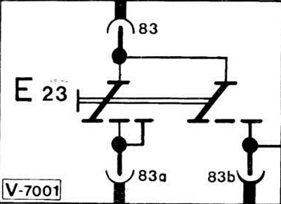
If switch E23 is set to the first position, current flows from terminal 83 through terminal 83a. In this case, the second direction of the switch is also switched, but the current circuit is not closed. Only when switched to the next position, the second direction of the switch supplies voltage from terminal 83 through the internal jumper to terminal 83b. In this case, the first direction of the switch continues to connect terminal 83 to terminal 83a.
For complex switch operation schemes (for example, a light switch) each corresponding functional part is depicted separately. The unity of the switch assembly is also expressed in its numbering.
Decoding the wire color codes
- BL — blue
- BR — brown
- GE - yellow
- GN - green
- GR — gray
- RT - red
- SW - black
- VI - purple
- WS — white
- TR — transparent
- RS - pink
- OR — orange
Designations of the most important elements
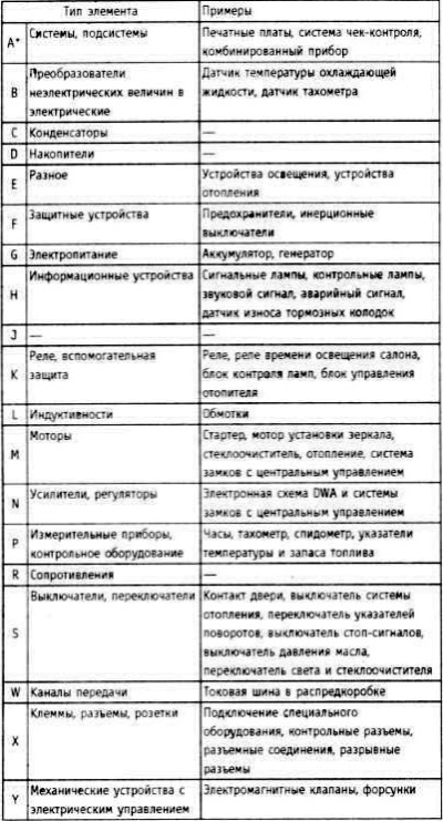
* For precise indication, letter designations are supplemented with ordinal numbering.
Example:
- S5 Light Switch
- 55.1 Instrument lighting switch
- 55.2 Parking light and number plate light switch
- 55.3 Headlight switch
Individual elements are considered in the explanations to the basic electrical circuits in groups with the same letter designation. The number behind the element reflects the location of the element, i.e. the current circuit in which the given element is located.
Example: H 17 Right brake light
- H — Designation of a group of elements (see "Designations of the most important elements")
- 17 - Current issue
Right brake light - Item name
- 130 — Position in the current circuit (at the bottom on the negative busbar)
- 130 in the rectangle is the connection point to the negative busbar
[The text is based on materials from the website «BMWMan.ru»]