
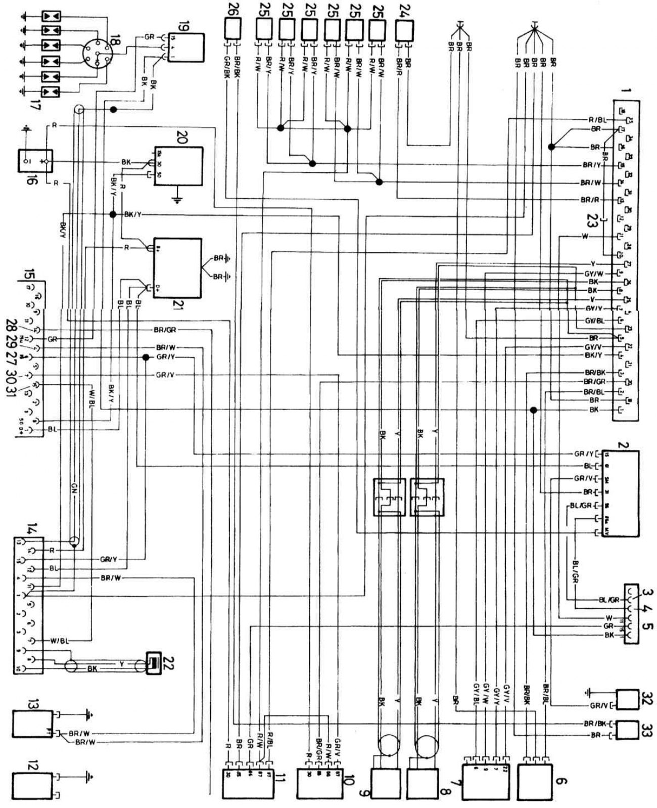
Schematic diagram of a typical Motronic engine management system
Open large image in new tab »
1 — Electronic Control Unit (ECU)
2 - Speed control relay
3 — Temperature sensor
4 — Air conditioning
5 - Vehicle wiring connector
6 - Throttle switch
7 — Air flow sensor
8 — Speed sensor
9 — Synchronization sensor
10 — Relay 1
11 — Relay2
12 — Oil pressure sensor
13 - Temperature transmitter
14 — Test connector
15 — Engine plug
16 — Battery
17 — Spark plugs
18 — Ignition distributor
19 — Ignition coil
20 — Starter
21 — Generator
22 — Position transmitter
23 - Plug disconnected for automatic transmission
24 — Coolant temperature sensor
25 — Fuel injector
26 — Solenoid valve
27 — Power distributor
28 — Oil pressure
29 — Temperature meter
30 - Electric fuel pump
31 — Scheduled maintenance reminder
32 — Drive motor
33 — Temperature sensor