
2. The engine oil temperature and pressure sensors are located on the oil filter base.
3. The temperature sensor in the control electronics compartment is installed directly in the compartment. To gain access to the sensor, remove the compartment cover. Disconnect the connector, release the clamps and remove the sensor.
Engine oil level sensor
1. Turn off the ignition and drain the engine oil.
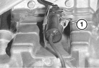
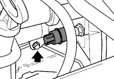
2. Disconnect the sensor connector located on the engine crankcase.
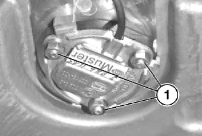
3. Give fixture and take out the sensor. Use a new gasket when installing.
Coolant temperature sensor
1. On the engine M51 remove the intake manifold (see chapter Engine), disconnect the connector and remove the sensor.
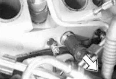
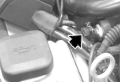
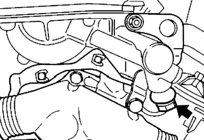
2. On the engine M52 The sensor is located at the front, under the intake manifold. Remove the injector cap (see chapter Power supply and exhaust systems) and disconnect the crankcase ventilation line. Disconnect the connector and unscrew the sensor.
3. On the engine M52TU The sensor is located under the intake manifold, in the cylinder head, next to cylinder #6. Remove the inlet pipeline, disconnect a socket and turn out the gauge.
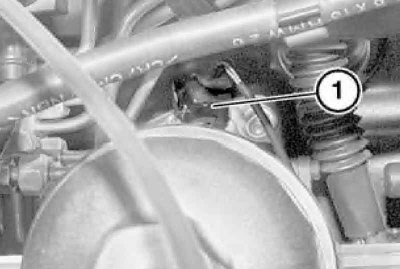
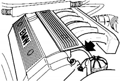
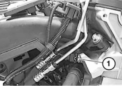
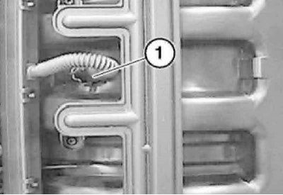
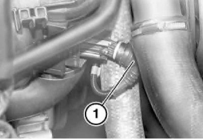
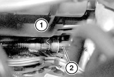
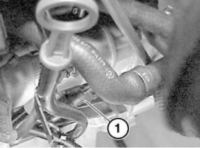
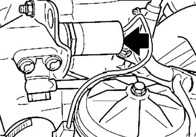
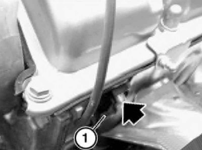
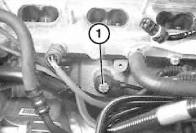
4. On the engine M60 sensor (1) located on the rear side of the expansion tank of the engine cooling system. Disconnect the connector and remove the sensor.
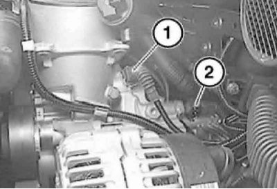
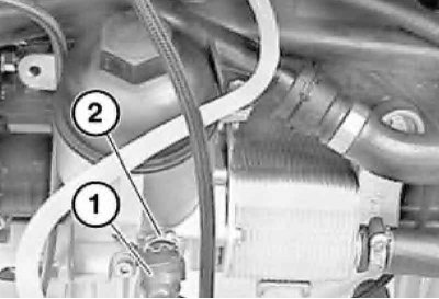
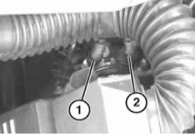
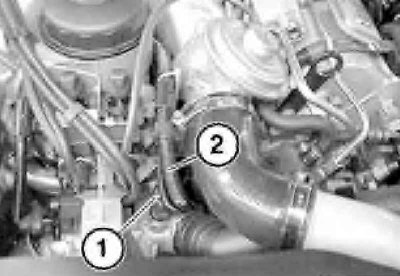
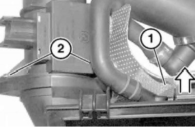
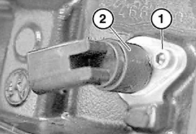
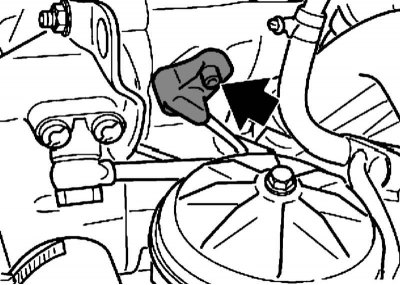
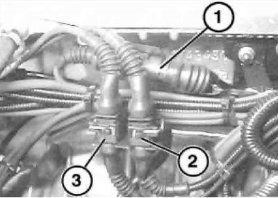
5. On the engine M62 with IAC valve Disconnect the connector and remove the sensor. At no IAC valve the coolant temperature sensor is installed in the front of the pipeline, - remove the vacuum pipes, disconnect the connector (2) and remove the sensor.
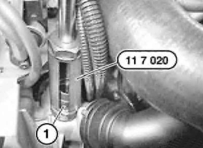
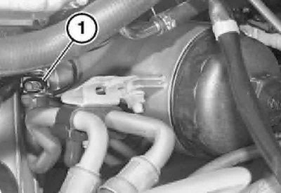
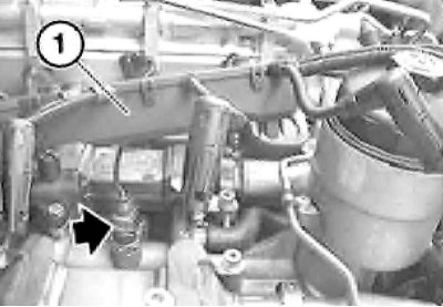
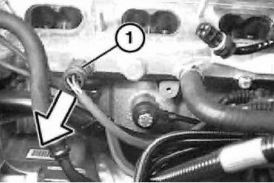
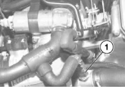
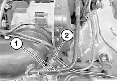
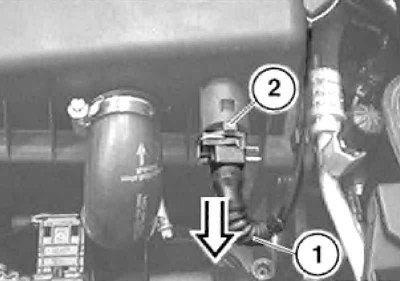
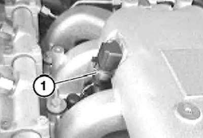
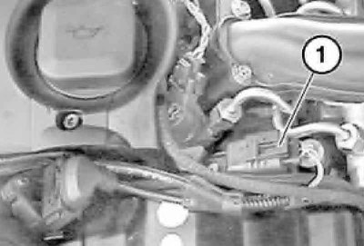
6. On the engine M67 remove disconnect connector (1) and move aside the wiring harness (2). Remove the sensor using the special tool.
When installing, replace the sensor O-ring if necessary.
Intake air temperature sensor (IAT)
1. On the engine M52 remove throttle body (see chapter Power supply and exhaust systems).
The drive cables and the throttle body heating system remain connected. Separate a socket, wring out a clamp and remove the gauge.
Engine IAT sensor M52
2. On the engine M52TU remove the injector cap (see chapter Power supply and exhaust systems). Separate a socket, wring out a clamp and remove the gauge.
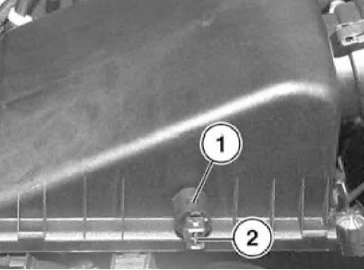
3. On engines M60 and M62 remove the engine top cover. On the engine M60 the sensor is built into the suction pipe, - depress the fixing spring, disconnect the connector and unscrew the sensor. On the engine M62 The IAT sensor is attached to the top of the air cleaner housing.
4. On the engine M73 depress the retaining spring, disconnect the connector, depress the retainer and remove the sensor.
Air flow sensor (MAF)
M51 engine
1. Remove the air cleaner housing (see chapter Power supply and exhaust systems).
2. Disconnect the connector.
3. Loosen clamp (1) attaching the hose to the turbocharger and disconnect the air supply hose to the MAF sensor.
4. Raise the MAF sensor with the air cleaner housing slightly so that the clamp can be loosened (1) hose attachments. Remove the air cleaner housing together with the air flow meter.
5. Press the spring clips on the left and right and remove the heat shield (1). Remove the bolts (2).
When installing, check the condition of the MAF sensor O-ring and replace the O-ring if necessary.
M52 engine
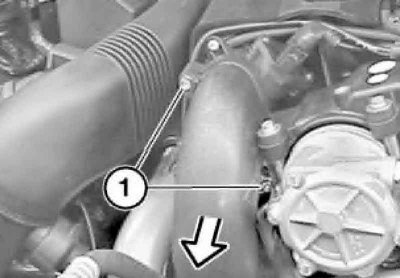
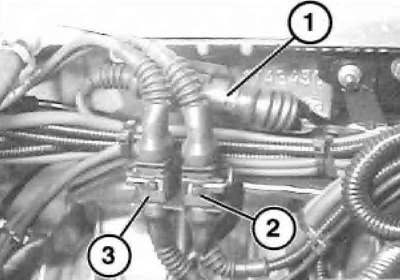
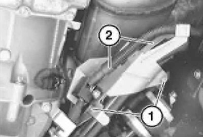
1. Loosen clamp (1), wring out the staples (2), disconnect the connector (3) and remove the MAF sensor.
2. When installing, check the condition of the gasket between the MAF sensor and the upper part of the air cleaner and replace it if necessary.
M52TU engine
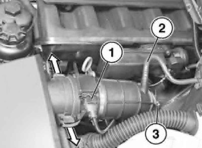
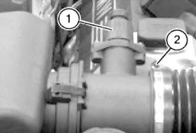
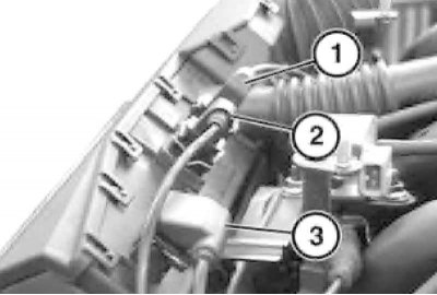
1. Disconnect the connector (1) MAF sensor, disconnect the vacuum hose (2) from the suction hose. Loosen clamp (3) hose attachments.
2. Release the clamps on the air cleaner housing and disconnect the suction hose with the MAF sensor.
3. When installing, check the condition of the gasket between the MAF sensor and the upper part of the air cleaner and replace it if necessary. Do not install a MAF sensor with a damaged grille.
M57 engine
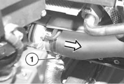
1. Remove the engine top cover and engine cooling fan shroud.
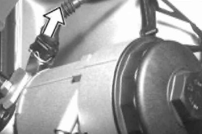
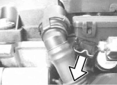
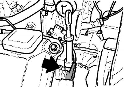
2. Turn out bolts and disconnect soaking-up hose in the direction of an arrow.
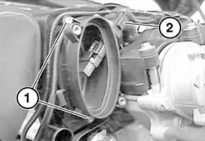
3. Disconnect the connector (2) MAF sensor, remove the bolts (1) and remove the sensor.
M60, M62, M73 engines
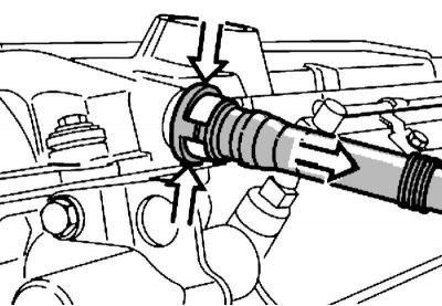
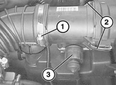
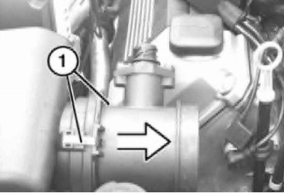
1. Disconnect the connector (1) MAF sensor, loosen clamp (2) and disconnect the suction hose from the MAF sensor.
2. Open the clips (1) and disconnect the MAF sensor from the top section of the air cleaner.
3. When installing, check the condition of the gasket between the MAF sensor and the upper part of the air cleaner and replace it if necessary.
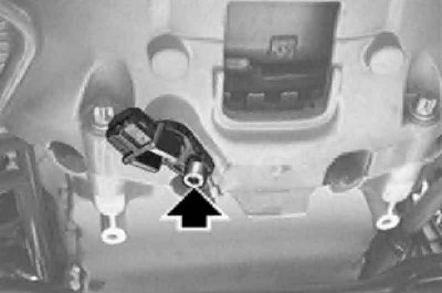
Boost pressure sensor
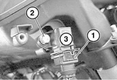
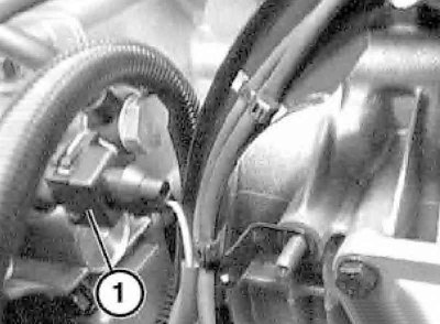
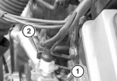
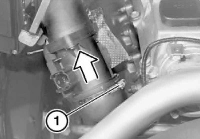
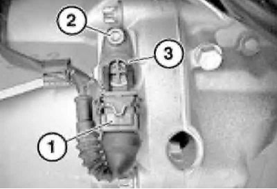
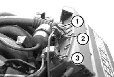
1. On the engine M57 the boost pressure sensor is mounted on the rear of the intake manifold - disconnect the connector (1) remove the bolt (2) and remove the sensor (3).
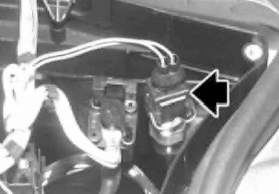
2. On the engine M67 remove the engine top cover, disconnect the boost pressure sensor connector, remove the bolt (to the left of the sensor) and remove the sensor.
3. At installation check up and if necessary replace a sealing ring of the gauge of pressure of boost.
Crankshaft position sensor (CKP)
M51 engine
1. The CKP sensor is installed under the starter.
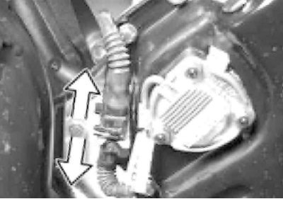
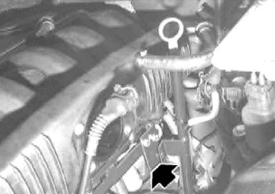
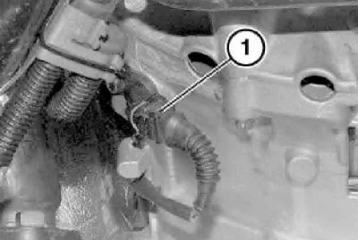
2. Move aside the radiator pipe at the engine inlet to see the mark (1) on the timing cover. Turn the crankshaft clockwise so that the mark on the damper (2) torsional vibration coincided with the label (1) on the timing cover. Disconnect the CKP sensor connector by pressing on the connector retaining clip.
3. Turn out a bolt, remove the CKP sensor together with the holder and disconnect the sensor from the holder.
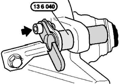
4. Place tool no. 13 6 040 on the holder, place the holder on the cylinder block and slide forward as far as it will go. This sets the required interval (A) between dowel pin on flywheel and CKP sensor. Fasten the holder.
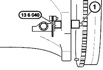
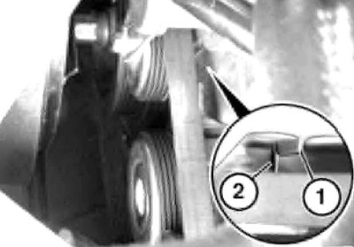
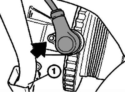
5. Now that the tool is close to the centering pin (1) flywheel reference signal, remove the tool from the holder.
Do not unscrew the holder on the cylinder block any more.
6. Install new the CKP sensor into the holder and dock the electrical wiring connector.
M52 engine
1. The CKP sensor is installed under the starter, - remove the air cleaner housing, unscrew the bolt and remove the sensor.
2. Disconnect the connector (2) electrical wiring under the intake manifold.
M57, M60, M62, M73 engines
1. On the engine M60 remove the engine top cover.
2. Disconnect the CKP sensor harness connector.
3. Remove the bolt and remove the CKP sensor.
4. On engines M62 and M73 When replacing the gearbox, flywheel or CKP sensor, note that if one or more shims are installed between the sensor and the gearbox housing, the distance between the sensor and the rotor teeth must be measured. To do this, turn the crankshaft by the central bolt clockwise forward so that through the hole of the removed CKP sensor you can see completely one rotor tooth exactly in the center of the hole. Measure the distance from the flange of the sensor socket to the rotor tooth and subtract the distance from the mating surface of the sensor to its end from the result. The resulting value is the gap distance between the sensor and the rotor and should be 0.55±0.2 mm. If necessary, adjust the gap using washers installed under the sensor.
M67 engine
1. Remove the rear crankcase guard, disconnect the negative cable from the battery.
2. Remove the bolts (1) and take the positive wire (2) battery to the side.
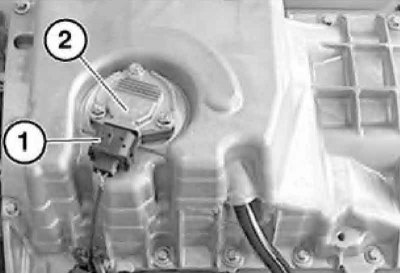
3. Disconnect the connector (1), remove the bolt (2) and remove the CKP sensor (3).
Camshaft position sensor (CMP)
M52 engine
1. Remove the protective cover of the injectors and disconnect the connector of the e / m valve of the timing phase adjustment system (Vanos) on the injector mounting plate.
2. Remove the Vanos solenoid valve.
During installation, check and, if necessary, replace the sealing gasket.
3. Disconnect the hydraulic line from the Vanos system activator.
4. Turn out a bolt of fastening of the gauge CMP and disconnect a socket of its electroconducting under the inlet pipeline (3).
Use a new screw when installing. Check and, if necessary, replace the gasket.
M57, M60, M62 engines
1. Remove the engine top cover and disconnect the CMP sensor connector.
2. Turn out a bolt and remove the gauge.
During installation, check and, if necessary, replace the sensor O-ring.
M73 engine
1. Remove the cover of the left ignition distributor with I/O wires (see Section Replacing the ignition distributor rotors).
2. Turn out a bolt and remove the gauge.
During installation, check and, if necessary, replace the sensor O-ring.
Knock sensor
Do not confuse the wiring of the knock sensors when connecting its connectors, as this may damage the engine.
1. Remove the inlet pipeline.
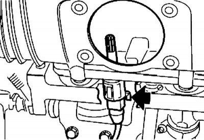
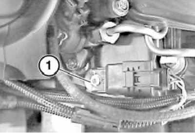
2. On the engine M52 disconnect connector (1).
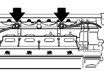
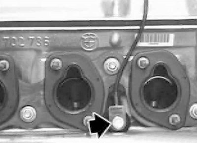
3. Turn out bolts and remove sensors of a detonation.
4. Before installing sensors, clean their mating surfaces.