
- Home
- BMW 7 Series
- E38
- Power unit
- Fuel system (petrol)
- Removal and installation of fuel distribution line and injectors
Removal and installation of fuel distribution line and injectors (BMW 7 Series E38)
Models with M52 engine
1. Turn off the ignition.
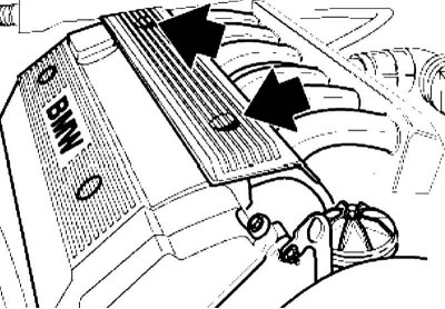
2. Remove the bolt caps and unscrew them. Remove the injector cover.
3. Disconnect the VANOS solenoid valve wiring connector. Press the latches and disconnect the lambda probe wiring connectors. Remove and set aside the injector connector mounting plate.
4. Mark the fuel supply and return lines to avoid confusion during subsequent installation, then disconnect the fuel lines from the fuel distribution line.
Replace O-rings or other damaged parts if necessary.
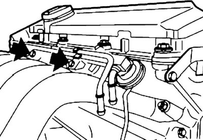
5. Remove the bolts and disconnect the vacuum hose from the fuel pressure regulator. Remove the fuel rail together with the injectors by pulling it upwards.
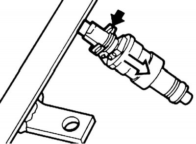
6. After removing the retainer, remove the injector.
7. Installation is carried out in reverse order.
Models with M52TU engine
1. Turn off the ignition.
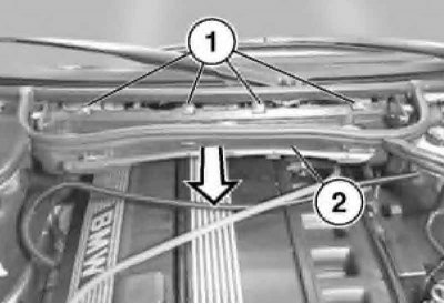
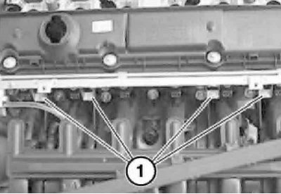
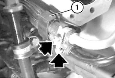
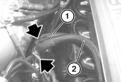
2. Remove the cabin filter and open the cable channel located on the lower part (2) of its housing. Pull the cables out. Unscrew the bolts (1) and remove the lower part (2) of the cabin filter housing.
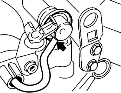
3. Remove the bolt caps and unscrew them. Remove the injector cover (see illustration).
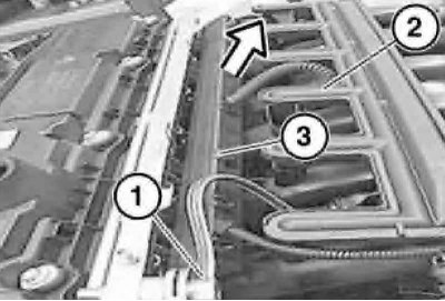
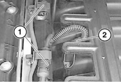
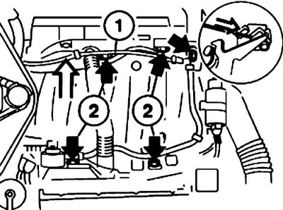
4. Disconnect the vacuum hose (1) from the fuel pressure regulator. Disconnect the IAT sensor wiring connector (2) and remove the injector mounting plate (3).
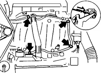
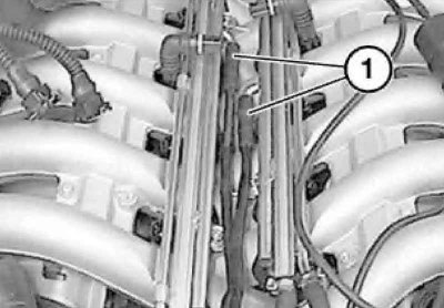
5. Mark the connectors (1) of the lambda probe wiring for cylinder groups No.1-3 and No.4-6 to avoid mixing them up during subsequent installation. Press the latches and disconnect the connectors. Remove the connector holders from the fuel distribution line.
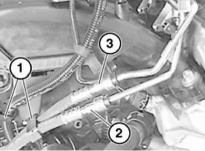
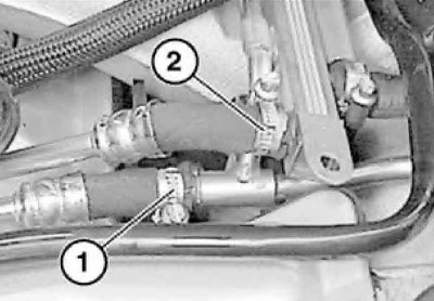
6. Mark the fuel supply and return lines (2 and 3) to avoid confusion during subsequent installation. Remove the fuel line retainers from the rear of the cylinder head. Replace the sealing rings or other damaged parts if necessary.
7. Unscrew the bolts and remove the fuel distribution line together with the injectors.
8. Remove the injectors if necessary.
9. Installation is carried out in the reverse order. To facilitate installation of the distribution line, lubricate the seals new injector rings with a sliding aid.
Models with M60 and M62 engines
1. Turn off the ignition.
2. Remove the top engine cover.
3. Remove the wire clamps. Disconnect the throttle cable from the throttle lever.
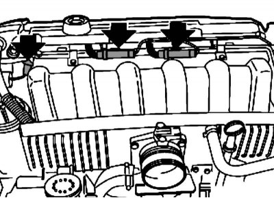
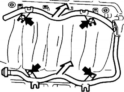
4. Remove the ignition coil covers from both sides of the cylinder head (see illustration).
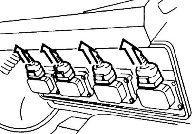
5. Disconnect the ignition coil connectors.
6. Remove the wiring boxes (2) and put them aside. Disconnect the injector wiring connectors.
7. Clamp the supply and return fuel lines and remove them. Collect the leaked fuel.
Use new hose clamps during installation.
8. Disconnect the vacuum hose from the fuel pressure regulator.
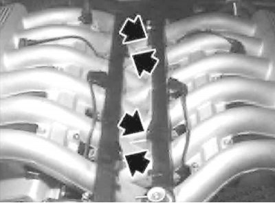
9. Unscrew the fuel distribution line mounting bolts and remove it together with the injectors.
10. If necessary, loosen the clamps and remove the injectors.
11. Installation is carried out in the reverse order. To facilitate installation of the distribution line, lubricate the seals new injector rings with a sliding aid.
Models with M73 engine
1. Turn off the ignition.
2. Disconnect the engine wiring connectors, lift the wiring harness and secure it to the hood.
3. Disconnect the fuel hoses.
When installing, replace the hoses and their mounting clamps.
4. Unscrew the fuel distribution line mounting bolts and remove it together with the injectors.
5. If necessary, loosen the clamps and remove the injectors.
6. Installation is carried out in the reverse order. To facilitate the installation of the distribution line, lubricate the seals new injector rings with a sliding aid.
This article is available at russian, bulgarian, belarusian, ukrainian, serbian, croatian, romanian, polish, slovak, hungarian
Article verified: Polikarpov Saveliy
Share information:
Previous articles
БМВ E38: Fuel system (petrol)
Next articles
Similar articles on other types of BMW cars:
Mechanical fuel pump — checking, adjustment, removal and installation BMW 3 Series E21 (1975-1983)
Fuel system expansion tank — removal and installation BMW 3 Series E46 (1998-2006, petrol)
Removal and installation the fuel pump BMW 5 Series E34 (1988-1996)
Removal and installation the fuel level sensor / fuel pump BMW 5 Series E39 (1995-2003)
Removal and installation the fuel filler cap BMW X3 E83 (2003-2010)
Removal and installation of injectors BMW X5 E53 (1999-2006)
Link in different formats to this page
Visitor comments
No comments yet
- General information
- Introduction to guide
- Manual
- Maintenance
- Power unit
- Engine M60/1, M60/2 (petrol)
- M62 engine (petrol)
- M57 engine (diesel)
- M67 engine (diesel)
- Cooling system
- Fuel system (petrol)
- Fuel system (diesel)
- Exhaust system
- Ignition and control systems
- Charge and launch systems
- Transmission
- Clutch
- Mechanical gearbox
- Automatic gearbox
- Cardan and drive shafts
- Chassis
- Brake system
- Front suspension
- Rear suspension
- Steering
- Body
- Exterior
- Interior
- Electrical equipment
- Equipment and devices
- Lighting
- Heating and air conditioning
- Electrical circuits
- General information
- Care and maintenance
- Power unit
- Minor engine repair
- Engine overhaul
- Lubrication system
- Cooling system
- Ignition system
- Supply system
- Injection system (petrol)
- Injection system (diesel)
- Exhaust system
- Transmission
- Clutch
- Manual gearbox
- Automatic gearbox
- Cardan gear
- Rear axle and shafts
- Chassis
- Front suspension
- Rear suspension
- Steering
- Wheels and tires
- Brake system
- Body
- Body elements
- Electrical equipment
- Equipment and devices
- Electrical circuits