
- Home
- BMW 3 Series
- E46
- Power unit
- Ignition system
- Basic information about the electronic engine management system
Basic information about the electronic engine management system (BMW 3 Series E46)
Electronic Digital Management of Petrol Engines (DME)
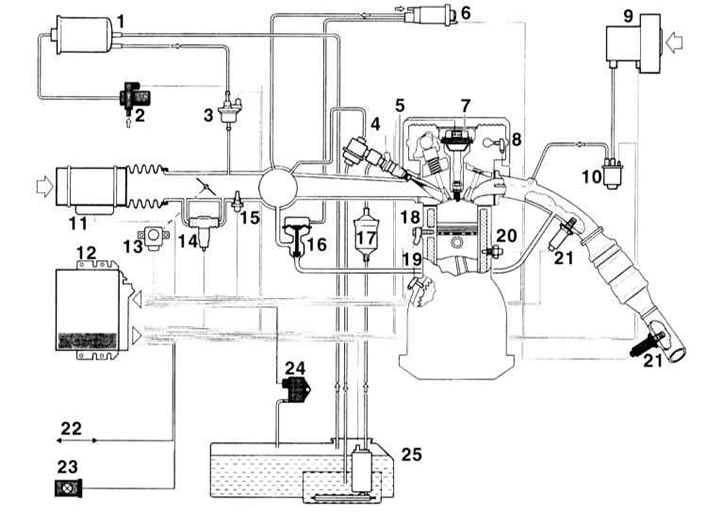
1 — adsorber
2 - shut-off valve
3 — fuel tank ventilation valve
4 — fuel pressure regulator
5 — injector
6 — pressure regulator
7 — ignition coil
8 — position sensor
9 — secondary air pump
10 - shut-off valve
11 - air mass meter
12 — control device
13 - throttle position sensor
14 — idle speed control
15 - air temperature sensor
16 — exhaust gas recirculation valve
17 — fuel filter
18 - knock sensor
19 — speed sensor
20 - engine temperature sensor
21 - oxygen sensor
22 — diagnostic connector
23 - diagnostic indicator lamp
24 - differential pressure sensor
25 - fuel pump
The electronic engine management system allows:
- Reduce the content of harmful substances in exhaust gases by precisely setting the ignition timing under any engine operating conditions.
- Increase the power of the ignition spark on a gasoline engine and, consequently, the reliability of starting and the stability of its operation.
- Self-diagnosis of the engine management system provides the ability to quickly find a fault. The engine management system has a fault memory. If a defect is detected during operation, it is entered into the device's memory. Using special devices, you can display a list of faults, allowing you to eliminate the defect yourself. See also Section Troubleshooting. It is advisable to carry out the work in a service station.
The engine control unit is a high-speed minicomputer. Among other things, it determines the optimal ignition timing on a gasoline engine, and on a diesel engine, it switches on the glow plugs via a relay. At the same time, the control unit is coordinated with other vehicle systems, such as the gearbox control system or theft protection system.
The engine management system elements maintain their high performance for a long time and require virtually no maintenance. Only spark plugs require replacement during maintenance. Serious adjustment and repair work requires the use of complex diagnostic devices. Refer to Section Troubleshooting. It is advisable to carry out the work in a service station.
Adjustment of ignition timing on gasoline engines is not required as part of maintenance.
Due to the good starting characteristics of the direct injection diesel engine, preheating is required mainly at temperatures below 0°C.
Information from various sensors and commands to the actuators ensure optimal engine operation in any mode. If the sensors fail, the control unit switches to emergency mode to prevent engine damage and ensure the vehicle can continue moving. Sensor failure does not necessarily have to be felt as a deterioration in engine performance.
However, no later than the next exhaust gas inspection (AU), data on this will be entered into the engine management system fault memory.
- The ignition system has no moving parts, there is no traditional ignition distributor. Each spark plug has its own coil.
- The ignition voltage monitoring system switches off the DME unit if the voltage is too low (for example, due to damage to the cable). In this case, the engine cannot be started. This eliminates damage to the catalytic converter.
- The anti-knock control system is used to determine and regulate the optimal ignition timing for each cylinder. If a malfunction occurs in the ignition system, the fuel supply to the corresponding cylinder is stopped.
- The fuel pump relay is located in the relay box above the glove box. The relay supplies current to the fuel pump.
General description of the OBD self-diagnosis system
1. The OBD system includes several diagnostic devices that monitor individual parameters of the toxicity reduction systems and record detected failures in the on-board processor memory in the form of individual fault codes. The system also checks sensors and actuators, monitors vehicle maintenance cycles, and provides the ability to memorize even short-term failures during operation and clear the memory unit.
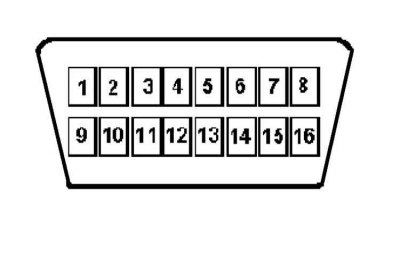
2. All gasoline models described in this Manual are equipped with a second-generation on-board diagnostics system (OBD-II). The main element of the system is the on-board processor, more often called the electronic control module (ECM) or the powertrain control module (PCM). The PCM is the brain of the engine management system. Initial data comes to the module from various information sensors and other electronic components (switches, relays, etc.). Based on the analysis of data received from the information sensors and in accordance with the basic parameters stored in the processor memory, the PCM generates commands to operate various control relays and actuators, thereby adjusting the operating parameters of the engine and ensuring maximum efficiency with minimum fuel consumption. Reading of the OBD-II processor memory data is performed using a special scanner connected to the 16-pin diagnostic connector for reading the database (DLC), located under the instrument panel on the driver's side of the car, or to the 20-pin connector located on the left in the engine compartment. Refer to the section Troubleshooting.
In principle, reading the fault codes stored in the self-diagnostic system memory can be done using the "Check Engine" lamp.
3. Special extended warranty terms apply to servicing of engine management/emission control system components. Do not attempt to diagnose ECM failures or replace system components on your own until these terms have expired - contact a specialist at a branded service station.
Information sensors
4. Oxygen sensors (λ-probes) - The sensor generates a signal, the amplitude of which depends on the difference in oxygen content (O2) in the engine exhaust gases and the outside air before and after the catalytic converter.
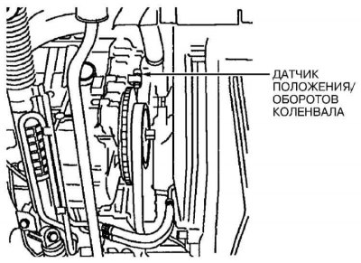
5. Crankshaft Position Sensor (CPS) - The sensor informs the PCM about the position of the crankshaft and engine speed. This information is used by the processor when determining the fuel injection timing and setting the ignition timing.
6. Piston Position Sensor (CYP) - Based on the analysis of signals received from the sensor, the PCM calculates the position of the piston of the first cylinder and uses this information to determine the timing and sequence of fuel injection into the engine combustion chambers.
7. TDC Sensor - The signals generated by the sensor are used by the PCM to determine the ignition timing settings at the time of engine start.
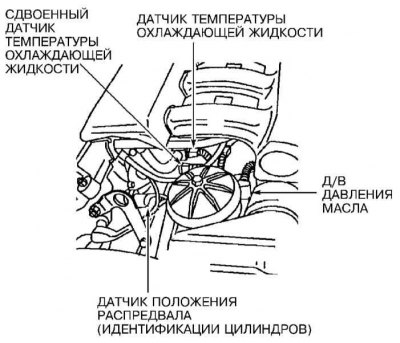
8. Engine coolant temperature sensor (ECT) - Based on the information received from the sensor, the ECM/PCM makes the necessary adjustments to the air-fuel mixture composition and ignition timing, and also monitors the operation of the EGR system.
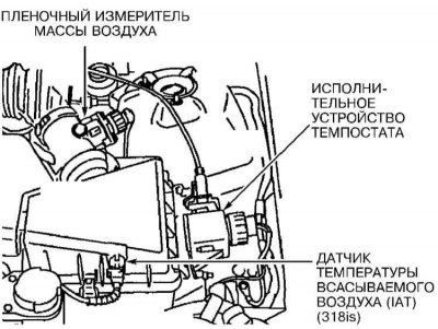
9. Intake Air Temperature (IAT) Sensor - The PCM uses information from the IAT sensor to make fuel flow adjustments, spark advance settings, and control EGR system operation.
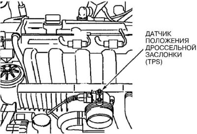
10. Throttle Position Sensor (TPS) - The sensor is located on the throttle body and is connected to the throttle shaft. Based on the amplitude of the signal emitted by the TPS, the PCM determines the opening angle of the throttle valve (controlled by the driver using the gas pedal) and accordingly adjusts the fuel supply to the combustion chamber intake ports. Sensor failure or loosening of its fastening leads to injection interruptions and disturbances in the stability of idle speed.
11. Manifold Absolute Pressure (MAP) Sensor - The sensor monitors variations in the depth of vacuum in the intake manifold associated with changes in crankshaft speed and engine load and converts the information received into an amplitude signal. The PCM uses the information supplied by the MAP and IAT sensors to make fine adjustments to fuel delivery.
12. Barometric pressure sensor - The sensor produces an amplitude signal proportional to changes in atmospheric pressure, which is used by the PCM to determine the duration of fuel injection moments. The sensor is built into the PCM module and is not subject to individual maintenance.
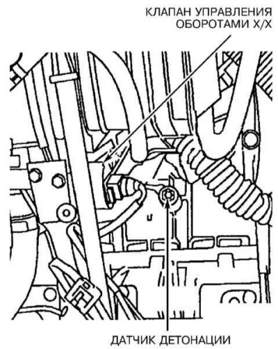
13. Knock sensor - The sensor reacts to changes in the vibration level associated with detonations in the engine. Based on the information received from the sensor, the PCM makes the appropriate adjustment of the ignition timing.
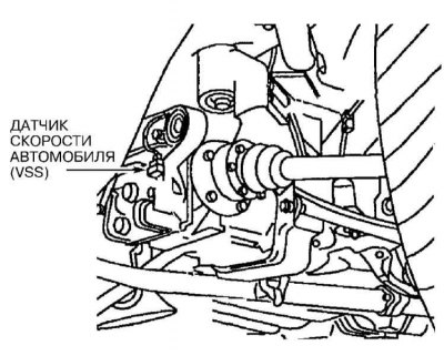
14. Vehicle Speed Sensor (VSS) - As its name suggests, the sensor informs the processor of the current speed of the vehicle.
15. EGR Valve Opening Amount Sensor - The sensor notifies the PCM of the amount of displacement of the EGR valve plunger. The received information is then used by the processor to control the operation of the exhaust gas recirculation system.
16. Fuel tank pressure sensor - The sensor is an integral part of the evaporative emission control system (EVAP) and is used to monitor the pressure of gasoline vapors in the tank. Based on the information received from the sensor, the PCM issues commands to operate the electromagnetic valves for purging the system.
17. Power Steering Pressure (PSP) Switch - Based on the information received from the PSP switch, the PCM increases the idle speed by activating the IAC sensor to compensate for the increased engine loads associated with the operation of the power steering during maneuvers.
18. Transmission Sensors - In addition to the data received from the VSS, the PCM also receives information from sensors located inside or connected to the transmission. These sensors include: (a) the secondary (main) shaft speed sensor and (b) the intermediate shaft speed sensor.
19. Air conditioner clutch control switch - When power is supplied from the battery to the electromagnetic valve of the air conditioner compressor, the corresponding information signal is sent to the PCM, which evaluates it as evidence of an increase in the load on the engine and adjusts its idle speed accordingly.
Executive devices
20. PGM-FI Main Relay (fuel pump relay) - The PCM activates the fuel pump relay when the ignition key is turned to the START or RUN position. When the ignition is turned on, the relay is activated to increase the pressure in the fuel system. More detailed information on the main relay is provided in Chapter Fuel, injection and exhaust systems.
21. Fuel injectors - the PCM ensures individual activation of each injector in accordance with the established firing order. In addition, the module controls the duration of the injector opening, determined by the width of the control pulse, measured in milliseconds and determining the amount of fuel injected into the cylinder. More detailed information on the operating principle of the injection system, replacement and maintenance of injectors is given in Chapter Fuel, injection and exhaust systems.
22. Ignition Control Module (ICM) - The module controls the operation of the ignition coil by determining the required base advance based on commands generated by the PCM. All vehicle models covered in this manual use an ICM built into the distributor, more details in this Chapter.
23. Idle Air Control Valve (IAC) - The IAC valve controls the amount of air bypassed around the throttle valve when the throttle valve is closed or at idle. The PCM controls the opening of the valve and the resulting air flow.
24. Carbon canister purge solenoid valve - The valve is an integral part of the fuel vapor recovery system (EVAP) and, when triggered by the PCM, releases the fuel vapors accumulated in the canister into the intake manifold for combustion during normal engine operation.
25. Canister Purge Control Solenoid - The solenoid is used by the PCM when the OBD-II system checks for proper operation of the EVAP system.
Reading fault codes
26. If a fault is detected that is repeated in two consecutive trips, the PCM issues a command to turn on the "Check Engine" warning lamp, also called the malfunction indicator, built into the instrument cluster. The lamp will remain lit until the self-diagnostic system memory is cleared of the codes of detected faults stored in it (refer to Specifications). Reading fault codes in the OBD-II system can be done in different ways. The main method is reading using the tools described in Section Troubleshooting devices connected to the 16-pin DLC connector of the OBD-II system. Other methods are not available on all models. The flashing code (defined by the manufacturer and different from the SAE "P" codes) can be read from the "Check Engine" lamp.
27. Without starting the engine, turn on the ignition - the "Check Engine" indicator lamp should light, otherwise it should be replaced. After checking the lamp's condition, turn off the ignition again.
Method for reading flashing codes from the "Check engine" lamp (possible on some models)
28. After turning on the ignition, fully depress and release the accelerator pedal five times within five seconds. If the processor memory contains codes of previous malfunctions, they will begin to be sequentially displayed by the "Check Engine" indicator lamp on the vehicle's dashboard. Read the flashing code.
The lamp waits for 5 seconds, one flash follows, then a code is issued with intervals of 2.5 seconds between the discharges. After the code is issued, the lamp remains lit. Repeat the procedure to read subsequent codes. If the first code issued is 1444, 2444 or 4444 - no malfunctions have been recorded.
Codes 1000 or 2000, given by one or two flashes and a long pause, followed by a constant lamp glow, indicate the end of the code output.
Flashing codes are different from the "P" codes listed in Specifications.
Starting the engine automatically interrupts access to the diagnostic system.
Clearing OBD-II memory
29. When a fault code is entered into the PCM memory, the "Check Engine" indicator light on the vehicle's instrument panel lights up. The code remains recorded in the module's memory.
30. To clear the ECM memory, connect a scanner to the system and select the CLEARING COEDS function in its menu (Removing codes). Then follow the instructions displayed on the instrument, or immediately remove the EFI fuse from its socket in the fuse box for 30 seconds. Alternatively, the system memory can be cleared by removing the fuse link (main fuse of the on-board electrical system), installed near the positive terminal of the battery (see chapter On-board electrical equipment) (you can also simply disconnect the positive cable from the battery).
It should be noted that clearing the OBD memory by disconnecting the negative battery cable will erase the engine settings and disrupt the stability of its speed for a short time after the initial start.
If your car stereo system is equipped with a security code, make sure you have the correct combination to activate the audio system before disconnecting the battery!
Disconnecting the battery also erases your receiver's favorite radio station settings.
To avoid damaging the ECM, disconnect and connect it only with the ignition off!
31. Ensure that the system memory is cleared before installing new emission control components on the engine. If the fault memory is not cleared before starting the system after replacing a failed information sensor, the PCM will enter a new fault code. Clearing the memory allows the processor to reconfigure to the new parameters. However, some instability of the engine speed may occur during the first 50 - 20 minutes after the initial start of the engine.
This article is available at russian, bulgarian, belarusian, ukrainian, serbian, croatian, romanian, polish, slovak, hungarian
Article verified: Sevastyanov Nikolay
Share information:
Previous articles
БМВ E46: Ignition system
Next articles
Similar articles on other types of BMW cars:
Digital electronic engine management system BMW 5 Series E34 (1988-1996)
General information about the engine management system BMW 5 Series E28 (1981-1988)
Replacing the sensors of the engine management system BMW 7 Series E38 (1994-2001)
Engine Overhaul. General Information BMW 7 Series E32 (1986-1994)
Exhaust system assembly (Engine M54 and N52 K) BMW X3 E83 (2003-2010)
Replacing the sensors of the engine management system BMW X5 E53 (1999-2006)
Link in different formats to this page
Visitor comments
No comments yet
- General information
- Manual
- Maintenance
- Power unit
- Engine repair
- Cooling system
- Power system (gasoline)
- Injection system (gasoline)
- Fuel system (diesel)
- Exhaust system
- Ignition system
- Charge and launch systems
- Transmission
- Car gearbox
- Clutch and drive shafts
- Chassis
- Brake system
- Suspension front and rear
- Steering
- Body
- Body care and repair
- Exterior
- Interior
- Electrical equipment
- Troubleshooting
- Lighting and signaling
- Equipment and devices
- Heater and air conditioner
- Electrical circuits
- General information
- Manual
- Repair on the road
- Weekly checks
- Maintenance
- Troubleshooting
- Power unit
- 4 cylinder engines
- 6 cylinder engines
- Engine overhaul
- Cooling and heating
- Fuel and exhaust system
- Starting and charging system
- Ignition system
- Transmission
- Clutch
- Mechanical gearbox
- Automatic gearbox
- Cardan and drive shafts
- Chassis
- Brake system
- Wheel suspension
- Steering
- Body
- Exterior
- Interior
- Electrical equipment
- Equipment and devices
- Electrical circuits
- General information
- Maintenance
- Power unit
- Engine repair
- Cooling system
- Ignition system
- Supply system
- Fuel injection system
- Exhaust system
- Transmission
- Clutch
- Car gearbox
- Front and rear axle
- Chassis
- Steering
- Brake system
- Body
- Exterior
- Interior
- Electrical equipment
- Heating system
- Equipment and devices
- Power devices
- Electrical circuits
- Power unit
- M10/M20 engine
- M40 engine
- Ignition system
- Lubrication system
- Cooling system
- Supply system
- Fuel injection
- Exhaust system
- Transmission
- Clutch
- Manual gearbox
- Front axle
- Rear axle
- Chassis
- Steering
- Brake system
- Body
- Exterior
- Interior
- Electrical equipment
- Heating system
- Equipment and devices
- Electrical circuits
- General information
- Specifications
- Operation and maintenance
- 4-cylinder engine
- Engine repair
- Cooling and lubrication system
- Supply system
- Ignition system
- 6-cylinder engine
- Engine repair
- Cooling and lubrication system
- Supply system
- Fuel injection system
- Ignition system
- Transmission
- Clutch
- 4-speed manual gearbox
- 5-speed manual gearbox
- Automatic gearbox
- Cardan and rear axle
- Chassis
- Steering
- Front suspension
- Rear suspension
- Brake system
- Electrical equipment
- Equipment and devices
- Electrical circuits