
- Home
- BMW 3 Series
- E46
- Electrical equipment
- Equipment and devices
- On-board electrical equipment specifications
On-board electrical equipment specifications (BMW 3 Series E46)
Individual characteristics are also given in the text of the Chapter and, if their implementation is mandatory, are highlighted in bold.
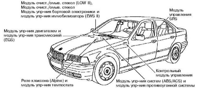
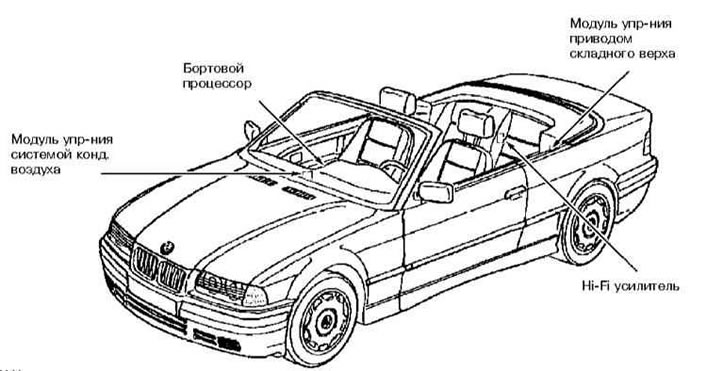
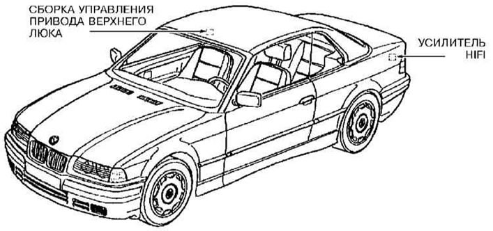
Location of electronic control units of vehicle systems on the body
| 12V incandescent lamps | Type | Power, W |
Low beam | H7 | 55 |
High beam | H1 | 55 |
Front turn signals | R | 21 |
| Front parking light | W | 5 |
| Front fog light | HB4 | 55 |
| Side turn signal repeater | W | 5 |
| Rear turn signal | P | 21 |
| Brake light/tail light | R | 21/4 |
| Reversing light | R | 21 |
| Rear fog light | R | 21 |
| License plate lighting | C11 | 5 |
| Additional brake light | lED strip1) | |
| Interior lighting | soffit | 5 |
| Reading light | XE | 6 |
| Backlighting of the leg and pocket area | soffit | 5 |
| Trunk/engine compartment lighting | soffit | 10 |
| Vanity mirror lighting | soffit | 10 |
| 1) If one LED fails, the entire brake light must be replaced. | ||
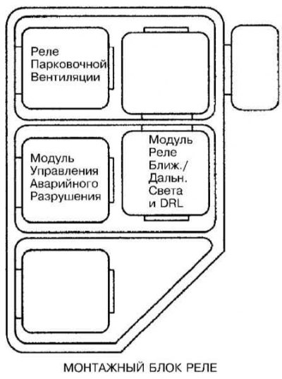
Relay and fuse boxes
Depends on the vehicle's equipment and year of manufacture. The fuse box diagram is located in the glove compartment under the fuse board.
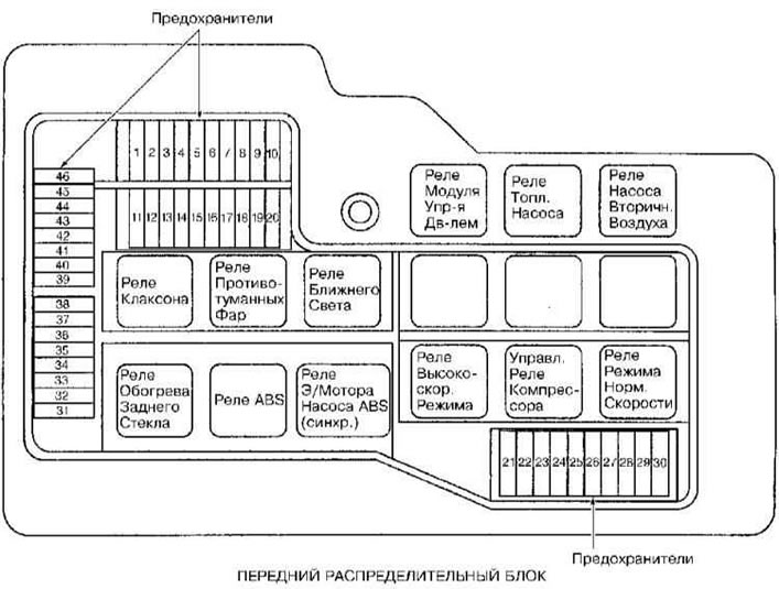
Location of fuses
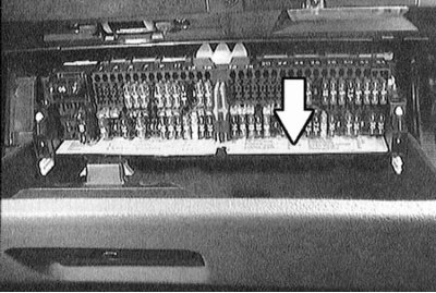
Relay box location behind glove box
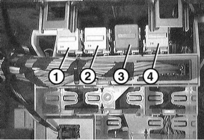
1 - fuel pump relay;
2 — heater fan relay
3 - fog light relay
4 - sound signal relay
Relay box in the engine compartment
Model 320d shown with cover removed
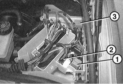
1 - DDE main relay (320d), ignition coil relay, terminal 15 (320i, 323i, 328i).
2 - Pre-heating control unit (320d), main relay DDE (all petrol engines)
3 - windshield wiper relay
Colour coding of fuses
| Current, A | Color coding |
| 5 | Light brown |
| 7.5 | Brown |
| 10 | Red |
| 15 | Blue |
| 20 | Yellow |
| 30 | Green |
Tightening forces of threaded connections
Tightening torques for fasteners are also given in the text of the Chapter and in some illustrations*.
* Tightening torques highlighted in bold in the text must be strictly observed; efforts not shown in bold are only approximate.
Cars of this brand are equipped with a 12 V electrical system with grounding on the negative pole. Power for all lighting devices and electrical units is provided by a lead-acid battery, recharged by an alternator.
This Chapter describes the maintenance and repair procedures for certain components of the on-board electrical system, which include, in addition to the specific components discussed below, all lighting fixtures and electrical accessories not directly related to the engine. In addition, diagnostic procedures for general electrical faults are discussed.
When performing any repair or maintenance work on components of the electrical system, it is imperative to first disconnect the negative cable from the battery to avoid electrical injury and/or fire.
This article is available at russian, bulgarian, belarusian, ukrainian, serbian, croatian, romanian, polish, slovak, hungarian
Article verified: Sevastyanov Nikolay
Share information:
Previous articles
БМВ E46: Equipment and devices
Next articles
Similar articles on other types of BMW cars:
Electrical equipment diagram for cars of the models «525», «525A»,… BMW 5 Series E12 (1972-1981)
Electrical Equipment System — General Information BMW 5 Series E39 (1995-2003)
On-board electrical equipment specifications BMW 7 Series E38 (1994-2001)
Electrical equipment. General information BMW 7 Series E32 (1986-1994)
Car electrical equipment — equipment and tools BMW X3 E83 (2003-2010)
General information about on-board electrical equipment BMW X5 E53 (1999-2006)
Link in different formats to this page
Visitor comments
No comments yet
- General information
- Manual
- Maintenance
- Power unit
- Engine repair
- Cooling system
- Power system (gasoline)
- Injection system (gasoline)
- Fuel system (diesel)
- Exhaust system
- Ignition system
- Charge and launch systems
- Transmission
- Car gearbox
- Clutch and drive shafts
- Chassis
- Brake system
- Suspension front and rear
- Steering
- Body
- Body care and repair
- Exterior
- Interior
- Electrical equipment
- Troubleshooting
- Lighting and signaling
- Equipment and devices
- Heater and air conditioner
- Electrical circuits
- General information
- Manual
- Repair on the road
- Weekly checks
- Maintenance
- Troubleshooting
- Power unit
- 4 cylinder engines
- 6 cylinder engines
- Engine overhaul
- Cooling and heating
- Fuel and exhaust system
- Starting and charging system
- Ignition system
- Transmission
- Clutch
- Mechanical gearbox
- Automatic gearbox
- Cardan and drive shafts
- Chassis
- Brake system
- Wheel suspension
- Steering
- Body
- Exterior
- Interior
- Electrical equipment
- Equipment and devices
- Electrical circuits
- General information
- Maintenance
- Power unit
- Engine repair
- Cooling system
- Ignition system
- Supply system
- Fuel injection system
- Exhaust system
- Transmission
- Clutch
- Car gearbox
- Front and rear axle
- Chassis
- Steering
- Brake system
- Body
- Exterior
- Interior
- Electrical equipment
- Heating system
- Equipment and devices
- Power devices
- Electrical circuits
- Power unit
- M10/M20 engine
- M40 engine
- Ignition system
- Lubrication system
- Cooling system
- Supply system
- Fuel injection
- Exhaust system
- Transmission
- Clutch
- Manual gearbox
- Front axle
- Rear axle
- Chassis
- Steering
- Brake system
- Body
- Exterior
- Interior
- Electrical equipment
- Heating system
- Equipment and devices
- Electrical circuits
- General information
- Specifications
- Operation and maintenance
- 4-cylinder engine
- Engine repair
- Cooling and lubrication system
- Supply system
- Ignition system
- 6-cylinder engine
- Engine repair
- Cooling and lubrication system
- Supply system
- Fuel injection system
- Ignition system
- Transmission
- Clutch
- 4-speed manual gearbox
- 5-speed manual gearbox
- Automatic gearbox
- Cardan and rear axle
- Chassis
- Steering
- Front suspension
- Rear suspension
- Brake system
- Electrical equipment
- Equipment and devices
- Electrical circuits