
Attention! After replacing the engine parameter sensors, it is necessary to read the fault information from the memory of the ECU-KSUD of the "DME" system. Eliminate the faults and erase the fault information from the memory of the ECU.
The engine crankshaft speed sensor is installed under the starter, its replacement must be carried out in the following order. Turn off the ignition and remove the stiffening plate. Unlock the SS and disconnect it from the engine crankshaft speed sensor (23 see fig. 3.3). Unscrew the screw (24) and remove the sensor.
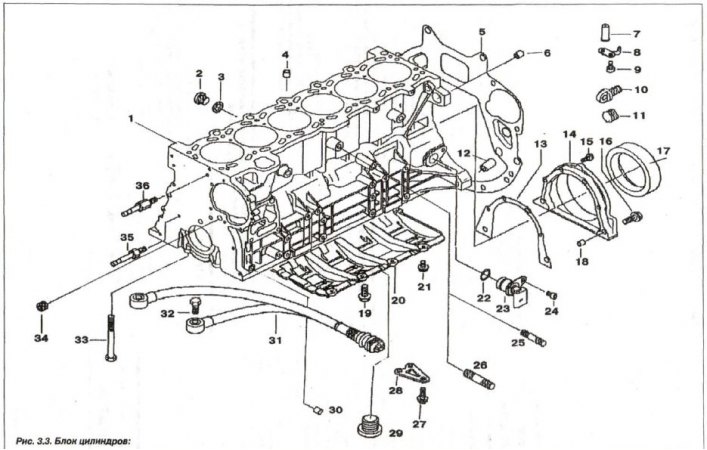
1 - cylinder block; 2 - threaded plug (M14x1.5); 3 - sealing ring; 4 - centering sleeve (∅ 13.5); S - shield; 6, 30 - centering sleeve (∅ 10.5); 7, 8 - nozzle; 9 - bolt (M6x16); 10 - plug; 11 - lid; 12 - centering sleeve (∅ 14.5); 13 - seal; 14 - oil seal cover; 15,16 - bolt (M8x32); 17 - oil seal; 18 - centering sleeve (∅ 10.5); 19 - bolt (M8x22); 20 - oil level regulator; 21 - bolt (M6x12); 22 - O-ring (17x3); 23 - crankshaft sensor; 24 - bolt (M6x16); 25 - stud (M8x35); 26 - stud (M10x40); 27 - bolt (M8x22); 28 - intermediate insert; 29 - threaded plug (M24x1.5); 30 - centering sleeve (∅ 13.5); 31 - knock sensor; 32 - bolt (M8x30); 33 - bolt (M10x92); 34 - threaded plug (M14x1.5); 35, 36 - cover pin
Intake camshaft position sensor (35, see Fig. 3.63) located on the cylinder head, its replacement must be carried out in the following order.
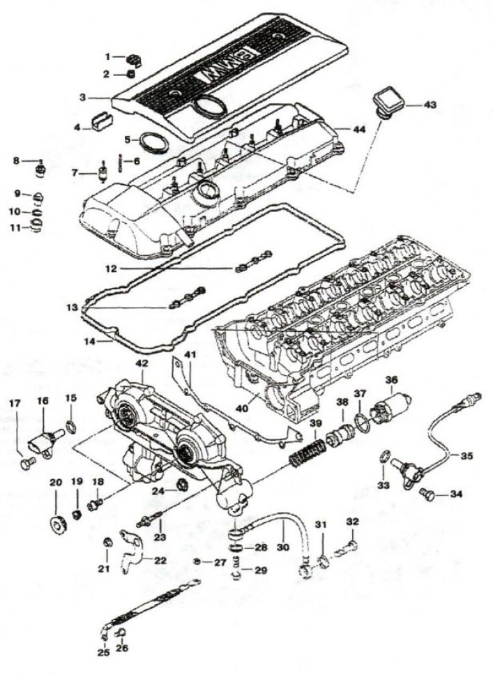
1, 19 - plug; 2 - nut; 3 - protective cover; 4 - overlay; 5, 28, 31, 33, 39 - sealing ring; 6, 23 - mounting pin; 7 - rubber-metal hinge; 8, 9 - cap nut; 10 - spacer washer; 11 - seal; 12, 13, 14 - profile gasket; 15, 37 - sealing ring (17x3); 16, 35 - camshaft sensor; 17, 34 - bolt (M6x16); 18 - precision bolt; 20 - plug with sealing ring; 21 - flange hook; 22 - fastening; 24 - nut M6; 25 - "mass" jumper; 26 - bolt (M6x10); 27 - nut M8; 29, 32 - hollow bolt; 30 - oil pipeline; 36 - EMC; 37 - ring (17x3); 38 - piston; 39 - spring; 40 - cylinder head; 41 - metal seal; 42 - actuator unit; 43 - oil filler cap; 44 - head cover
Switch off the ignition and remove the air filter housing. Remove the electromagnetic valve (36) of the D-VANOS system actuator of the intake camshaft. Disconnect the SG on the cable box.
Connect a section of auxiliary wire approximately 50–60 cm long to the sensor SS, which will make it easier to install the new sensor later. Loosen the screw (34) securing the sensor (35). Remove the sensor from the cylinder head. Pull the end of the sensor wire out so that the auxiliary cable fits into its place in the cable box. Remove the sensor together with the wire connecting it to the system. Disconnect the auxiliary wire from the faulty sensor. Fasten it to the auxiliary wire of the new sensor SS. Pull the cable of the new sensor into the cable box using the auxiliary wire.
Check the sealing ring (33) for possible damage and replace it if necessary. Replace the sealing ring (37) of the D-VANOS solenoid valve (36) and tighten the valve to a torque of 30 Nm (3.0 kgf·m).
Exhaust camshaft position sensor (16, see Fig. 3.63) is located in the front part of the cylinder head on the exhaust side, its replacement must be carried out in the following order. Turn off the ignition and disconnect the shock absorber from the sensor.
Loosen the bolt (17) securing the sensor to the cylinder head. Remove the pulse sensor (16) from the cylinder head. Check the sealing ring (15) for possible damage; replace it if necessary.
Knock sensors (31, see Fig. 3.3) are located on the engine cylinder block and must be replaced in the following order.
Switch off the ignition and remove the intake manifold. Release the knock sensor from the holder on the cable box and disconnect it. Unscrew the bolts (32) and remove the knock sensors from cylinder group 1-3 and from cylinder group 4-6.
When installing, clean the contact surface of the knock sensors and their installation locations on the cylinder block. Install the knock sensors and tighten the mounting bolts (32) to a torque of 20 N·m (2.0 kgf·m).
Lubrication system sensors (3 pcs.) are installed in two places. Two oil sensors are installed on the oil filter housing - temperature (10, see Fig. 3.16) and pressure (11), located diagonally.
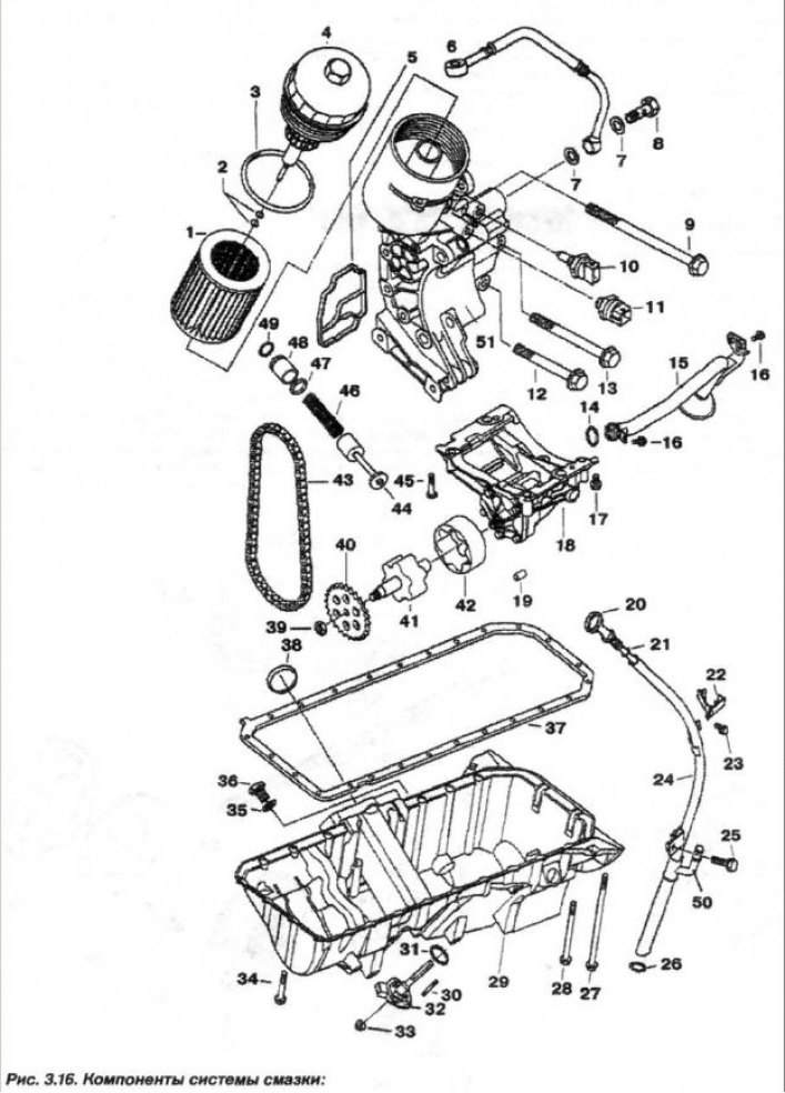
1 - replaceable element; 2 - ring (7.0x2.5); 3 - ring (91x4); 4 - filter cover; 5 - sealing gasket; 6 - oil pipeline; 7 - sealing ring (A14x20); 8 - hollow bolt; 9 - bolt (M8x100); 10 - oil temperature sensor; 11 - oil pressure sensor; 12 - bolt (M8x55); 13 - bolt (148x70); 14 - ring (20x3); 15 - suction pipe; 16 - bolt (M6x16); 17.45 - bolt (M8x55); 18 - oil pump; 19 - bushing; 20 - feeler gauge; 21 - ring (9x2.2); 22 - bracket; 23, 25, 27, 28, 34 - bolt; 24 - guide; 26 - ring (19.5x3); 29 - oil pan; 30 - pin (M6x30); 31, 35 - sealing ring; 32-oil level sensor; 33 - nut (M6); 36 - plug (M12x1.5); 37 - sealing gasket; 38 - mounting ring; 39 - nut (M10x1); 40 - asterisk; 41 - internal rotor; 42 - outer rotor; 43 - chain; 44 - control valve; 46 - spring; 47 - ring (17x1.8); 48 - spacer sleeve; 49 - retaining ring (2x1); 50 - oil separator hose branch pipe; 51 - oil filter housing
The temperature sensor is installed slightly higher.
The oil temperature sensor must be replaced in the following order. Switch off the ignition. Unscrew the cover (4) of the oil filter so that the oil flows into the oil pan. Remove the air filter housing. Disconnect the SS from the oil temperature sensor and unscrew the oil temperature indicator sensor.
When installing, tighten the oil temperature sensor to a torque of 27 N·m (2.7 kgf·m). Check the oil level and restore it if necessary.
The oil pressure sensor (11) must be replaced in the following order. Switch off the ignition. Unscrew the oil filter cover (4) so that the oil flows into the oil pan. Remove the air filter housing and disconnect the SS from the oil pressure sensor. Unscrew the oil pressure sensor.
When installing, tighten the oil pressure sensor to a torque of 27 N·m (2.7 kgf·m). Check the oil level and restore it if necessary.
Replacing the sensor (32, see Fig. 3.16) the oil level installed in the oil pan must be checked in the following order.
Turn off the ignition. Unscrew the oil filter cap so that the oil flows into the engine oil pan. Remove the stiffening plate, unscrew the plug (36) and drain the oil from the engine. Send the drained oil for disposal. Disconnect the SS from the oil level sensor.
Loosen the nuts (33) and remove the oil level sensor (32). Clean the sealing surface on the oil pan. Replace the sealing ring (31) of the oil level sensor and the sealing ring (3) of the cover (4) of the oil filter. Pay attention to the locking pin (30).
Replace and tighten the oil filter cover to 33 N·m (3.3 kgf·m). Install the stiffening plate and tighten it to 56 N·m + 90°. Fill the engine with oil and check its level.
Replacing the temperature sensor(19, see Fig. 3.18) the incoming air must be removed in the following order.
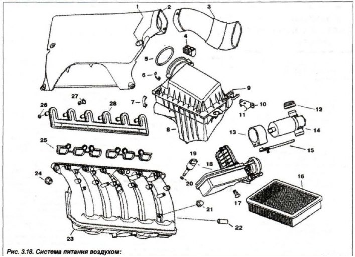
1 - rubber bushing; 2 - air intake; 3 - casing; 4 - shock absorber; 5 - ring (91x6); 6 - bracket (34 mm); 7 - snob (42 mm); 8 - muffler/housing; 9 - spacer sleeve; 10 - bracket; 11 - bolt (M6x12); 12 - socket; 13 - hinge; 14 - idle valve; 15 - valve bracket; 16 - replaceable filter element; 17 - bolt T (M6x18); 16 - actuator unit; 19 - temperature sensor; 20 - ring (8x3); 21 - Nut (MB); 22 - bushing; 23 - intake manifold; 24 - nut (M7); 25 - gaskets; 26 - ring (7X3); 27 - screw; 28 - transition
Turn off the ignition and remove the injector cover. Disconnect the HS from the inlet air temperature sensor. Press the retainer and remove the temperature sensor from the intake manifold.
When installing the sensor, check the sealing ring (20) for damage and replace the ring if it is damaged.
The accelerator pedal position sensor (gas) is located in the car's interior and is directly connected to the pedal. It must be replaced in the following order. Turn off the ignition. Carefully press the locking tab (1, Fig. 3.164) down and remove the accelerator pedal module (2) from the side.
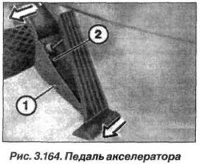
Disconnect the SS from the accelerator pedal module and remove the accelerator pedal position sensor.
Installation of the accelerator pedal position sensor should be carried out in the reverse order.
The coolant temperature sensor is installed under the exhaust manifold in the cylinder head, next to the 6th cylinder and must be replaced in the following order. Turn off the ignition and remove the intake manifold. Disconnect the SS (1, Fig. 3.165) and unscrew the coolant temperature sensor.
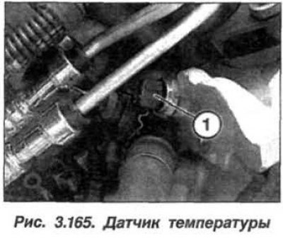
The temperature sensor should be installed in the reverse order, and the temperature sensor should be returned and tightened to 13 N·m (1.3 kgf·m). Assemble the engine, check the coolant level and restore it if necessary.
Replacing the idle air control valve. Idle air control valve (14, see Fig. 3.18) installed under the intake manifold, directly above the throttle valve.
The idle speed control valve must be replaced in the following order. Turn off the ignition and disconnect the "–" terminal from the battery. Remove the suction hose between the air filter housing and the throttle body. Disconnect the SS from the resonance valve (18) and from the idle speed control valve (14).
Remove the cable box mounting bolt and the idle air valve holder bolts (13). Remove the idle air valve from the intake manifold together with the bracket.
Remove the valve (2, Fig. 3.166) idle speed from the rubber bracket (4).
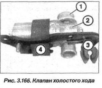
The sealing gasket (1) between the idle valve (2) and the intake manifold must be replaced. When replacing, first install the gasket on the intake manifold.
To facilitate installation of the idle control valve, lubricate the inside of the seal with sliding grease.
The fuel pump relay must be replaced in the following order. Read information from the fault memory of the DME ECU-KSUD system, turn off the ignition. Open the glove compartment and remove it.
Loosen the screws and remove the fuse box by moving it downwards (without disconnecting the control unit).
Remove the relay (1, Fig. 3.167) fuel pump.
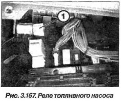
Attention! After removing the fuel pump relay, when turning the ignition key to the start position, the fuel pump does not turn on and the engine does not start.
The fuel pump relay should be installed in the reverse order, while it is necessary to read the information from the fault memory of the DME ECU KSUD. Check the recorded fault messages. Eliminate the faults and erase the information from the fault memory.
[This article is based on information from the website «BMWMAN.RU»]