
- Home
- BMW X5
- E53
- Electrical equipment
- Electrical circuits
Vehicle wiring diagrams BMW X5 E53
Electrical diagram symbols and explanations
Electrical diagrams of the BMW X5 series car, with the E53 body, are given by unit, since the saturation of wires is more than 12,500 m. The negative wire of...
Electrical diagrams of the BMW X5 series car, with the E53 body, are given by unit, since the saturation of wires is more than 12,500 m. The negative wire of...

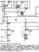
Starter Wiring Diagram (MS43)
Starter (MS43) For electrical circuit symbols and explanations of the circuits, see here →
Starter (MS43) For electrical circuit symbols and explanations of the circuits, see here →

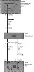
Starter control circuit diagram
Starter control For electrical circuit symbols and explanations of the circuits, see here →
Starter control For electrical circuit symbols and explanations of the circuits, see here →

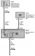
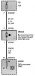
Electrical diagram of the power supply of the DME system ECU
Power supply for the DME system ECU For electrical circuit symbols and explanations of the circuits, see here →
Power supply for the DME system ECU For electrical circuit symbols and explanations of the circuits, see here →

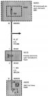
Voltage and current regulation circuit diagram (MS43)
Voltage and current regulation (MS43) For electrical circuit symbols and explanations of the circuits, see here →
Voltage and current regulation (MS43) For electrical circuit symbols and explanations of the circuits, see here →

Voltage and current regulation circuit diagram (ME7.2)
Voltage and current regulation (ME7.2) For electrical circuit symbols and explanations of the circuits, see here →
Voltage and current regulation (ME7.2) For electrical circuit symbols and explanations of the circuits, see here →

Voltage and current regulation circuit diagram (ME9)
Voltage and current regulation (ME9) For electrical circuit symbols and explanations of the circuits, see here →
Voltage and current regulation (ME9) For electrical circuit symbols and explanations of the circuits, see here →

Fuel pump wiring diagram
Fuel pump For electrical circuit symbols and explanations of the circuits, see here →
Fuel pump For electrical circuit symbols and explanations of the circuits, see here →

Electrical diagram of the indication function and information (MS43)
Indication functions and information (MS43) For electrical circuit symbols and explanations of the circuits, see here →
Indication functions and information (MS43) For electrical circuit symbols and explanations of the circuits, see here →

Electrical diagram of the flow meter
Electrical diagram of the flow meter For electrical circuit symbols and explanations of the circuits, see here →
Electrical diagram of the flow meter For electrical circuit symbols and explanations of the circuits, see here →

Electrical diagram of the mixture preparation/ignition system
Fuel mixture preparation/ignition systems For electrical circuit symbols and explanations of the circuits, see here →
Fuel mixture preparation/ignition systems For electrical circuit symbols and explanations of the circuits, see here →

Electrical diagram of the input parameters of the mixture/ignition system
Input Parameters of Mixture/Ignition Systems For electrical circuit symbols and explanations of the circuits, see here →
Input Parameters of Mixture/Ignition Systems For electrical circuit symbols and explanations of the circuits, see here →

Engine control/additional signals wiring diagram
Engine management/additional signals For electrical circuit symbols and explanations of the circuits, see here →
Engine management/additional signals For electrical circuit symbols and explanations of the circuits, see here →

Electrical diagram of the injector of the row 1
Injector row 1 For electrical circuit symbols and explanations of the circuits, see here →
Injector row 1 For electrical circuit symbols and explanations of the circuits, see here →

Electrical diagram of the injector of the 2nd row
Injector row 2 For electrical circuit symbols and explanations of the circuits, see here →
Injector row 2 For electrical circuit symbols and explanations of the circuits, see here →
Crankshaft Position Sensor Wiring Diagram
Crankshaft position sensor For electrical circuit symbols and explanations of the circuits, see here →
Crankshaft position sensor For electrical circuit symbols and explanations of the circuits, see here →

Electrical diagram of camshaft position
Camshaft position For electrical circuit symbols and explanations of the circuits, see here →
Camshaft position For electrical circuit symbols and explanations of the circuits, see here →

Electrical diagram of VANOS valves
VANOS valves For electrical circuit symbols and explanations of the circuits, see here →
VANOS valves For electrical circuit symbols and explanations of the circuits, see here →

Electrical diagram of the Valvetronic valve drive
Valvetronic valve drive For electrical circuit symbols and explanations of the circuits, see here →
Valvetronic valve drive For electrical circuit symbols and explanations of the circuits, see here →

Ignition Coil Wiring Diagram Bank 1
Ignition coil row 1 For electrical circuit symbols and explanations of the circuits, see here →
Ignition coil row 1 For electrical circuit symbols and explanations of the circuits, see here →

Ignition Coil Wiring Diagram Bank 2
Ignition coil bank 2 For electrical circuit symbols and explanations of the circuits, see here →
Ignition coil bank 2 For electrical circuit symbols and explanations of the circuits, see here →

Electrical diagram of the separate suction system
Separate suction system For electrical circuit symbols and explanations of the circuits, see here →
Separate suction system For electrical circuit symbols and explanations of the circuits, see here →

Electrical diagram of the knock control system
Knock control system For electrical circuit symbols and explanations of the circuits, see here →
Knock control system For electrical circuit symbols and explanations of the circuits, see here →

Electrical diagram of the engine cooling system
Engine cooling system For electrical circuit symbols and explanations of the circuits, see here →
Engine cooling system For electrical circuit symbols and explanations of the circuits, see here →

Electrical diagram of the engine lubrication system
Engine lubrication system For electrical circuit symbols and explanations of the circuits, see here →
Engine lubrication system For electrical circuit symbols and explanations of the circuits, see here →

Accelerator Pedal Module Wiring Diagram
Accelerator Pedal Module For electrical circuit symbols and explanations of the circuits, see here →
Accelerator Pedal Module For electrical circuit symbols and explanations of the circuits, see here →

Electrical diagram of diesel engine starter control
Diesel Engine Starter Control For electrical circuit symbols and explanations of the circuits, see here →
Diesel Engine Starter Control For electrical circuit symbols and explanations of the circuits, see here →

Electrical circuit for voltage and current regulation (diesel)
Voltage and current regulation (diesel) For electrical circuit symbols and explanations of the circuits, see here →
Voltage and current regulation (diesel) For electrical circuit symbols and explanations of the circuits, see here →

Air flow meter wiring diagram (diesel)
Air flow meter (diesel) For electrical circuit symbols and explanations of the circuits, see here →
Air flow meter (diesel) For electrical circuit symbols and explanations of the circuits, see here →
Electrical diagram of the throttle valve with electric drive (diesel)
Electric throttle (diesel) For electrical circuit symbols and explanations of the circuits, see here →
Electric throttle (diesel) For electrical circuit symbols and explanations of the circuits, see here →

Electrical diagram of the engine cooling system (diesel)
Engine cooling system (diesel) For electrical circuit symbols and explanations of the circuits, see here →
Engine cooling system (diesel) For electrical circuit symbols and explanations of the circuits, see here →

Electrical diagram of the engine lubrication system (diesel)
Engine lubrication system (diesel) For electrical circuit symbols and explanations of the circuits, see here →
Engine lubrication system (diesel) For electrical circuit symbols and explanations of the circuits, see here →

Fuel pump wiring diagram (diesel)
Fuel pump (diesel) For electrical circuit symbols and explanations of the circuits, see here →
Fuel pump (diesel) For electrical circuit symbols and explanations of the circuits, see here →

Fuel supply wiring diagram (diesel)
Fuel supply (diesel) For electrical circuit symbols and explanations of the circuits, see here →
Fuel supply (diesel) For electrical circuit symbols and explanations of the circuits, see here →

Electrical circuit for measuring crankshaft speed (diesel)
Crankshaft speed measurement (diesel) For electrical circuit symbols and explanations of the circuits, see here →
Crankshaft speed measurement (diesel) For electrical circuit symbols and explanations of the circuits, see here →

Electrical diagram of exhaust gas sensors (diesel)
Exhaust gas sensors (diesel) For electrical circuit symbols and explanations of the circuits, see here →
Exhaust gas sensors (diesel) For electrical circuit symbols and explanations of the circuits, see here →

Light switch wiring diagram
Light switch For electrical circuit symbols and explanations of the circuits, see here →
Light switch For electrical circuit symbols and explanations of the circuits, see here →

Right turn signal wiring diagram
Right turn signal For electrical circuit symbols and explanations of the circuits, see here →
Right turn signal For electrical circuit symbols and explanations of the circuits, see here →

Left turn signal wiring diagram
Left turn signal For electrical circuit symbols and explanations of the circuits, see here →
Left turn signal For electrical circuit symbols and explanations of the circuits, see here →

Wiring diagram for headlight direction switch
Headlight direction switch For electrical circuit symbols and explanations of the circuits, see here →
Headlight direction switch For electrical circuit symbols and explanations of the circuits, see here →

Lighting power supply circuit
Lighting power supply For electrical circuit symbols and explanations of the circuits, see here →
Lighting power supply For electrical circuit symbols and explanations of the circuits, see here →

Lighting wiring diagram
Lighting wiring diagram For electrical circuit symbols and explanations of the circuits, see here →
Lighting wiring diagram For electrical circuit symbols and explanations of the circuits, see here →

Front body lighting wiring diagram
Front body lighting For electrical circuit symbols and explanations of the circuits, see here →
Front body lighting For electrical circuit symbols and explanations of the circuits, see here →

Wiring diagram for front passenger compartment lighting
Front passenger compartment lighting For electrical circuit symbols and explanations of the circuits, see here →
Front passenger compartment lighting For electrical circuit symbols and explanations of the circuits, see here →

Electrical diagram of rear headlights, brake lights
Rear headlights, brake lights For electrical circuit symbols and explanations of the circuits, see here →
Rear headlights, brake lights For electrical circuit symbols and explanations of the circuits, see here →

Fog lights wiring diagram
Fog lights For electrical circuit symbols and explanations of the circuits, see here →
Fog lights For electrical circuit symbols and explanations of the circuits, see here →

Wiring diagram for license plate lights
License plate lights For electrical circuit symbols and explanations of the circuits, see here →
License plate lights For electrical circuit symbols and explanations of the circuits, see here →

Brake light switch wiring diagram
Brake light switch For electrical circuit symbols and explanations of the circuits, see here →
Brake light switch For electrical circuit symbols and explanations of the circuits, see here →

Electrical diagram of the hazard warning switch
Hazard warning switch For electrical circuit symbols and explanations of the circuits, see here →
Hazard warning switch For electrical circuit symbols and explanations of the circuits, see here →

Wiring diagram for luggage door control
Trunk door control For electrical circuit symbols and explanations of the circuits, see here →
Trunk door control For electrical circuit symbols and explanations of the circuits, see here →

Rear window lifter wiring diagram
Rear window lifter For electrical circuit symbols and explanations of the circuits, see here →
Rear window lifter For electrical circuit symbols and explanations of the circuits, see here →

Front window lifter wiring diagram
Front window lifter For electrical circuit symbols and explanations of the circuits, see here →
Front window lifter For electrical circuit symbols and explanations of the circuits, see here →
Fuel tank ventilation valve wiring diagram
Fuel tank ventilation valve For electrical circuit symbols and explanations of the circuits, see here →
Fuel tank ventilation valve For electrical circuit symbols and explanations of the circuits, see here →

Electrical diagram of the functions of washers and wipers
Washer and wiper functions For electrical circuit symbols and explanations of the circuits, see here →
Washer and wiper functions For electrical circuit symbols and explanations of the circuits, see here →
Electronics Compartment Fan Wiring Diagram
Electronics compartment fan For electrical circuit symbols and explanations of the circuits, see here →
Electronics compartment fan For electrical circuit symbols and explanations of the circuits, see here →

Rain intensity sensor wiring diagram
Rain intensity sensor For electrical circuit symbols and explanations of the circuits, see here →
Rain intensity sensor For electrical circuit symbols and explanations of the circuits, see here →

Tire Pressure Monitoring System (RDC) Wiring Diagram
Tire Pressure Monitoring System (RDC) For electrical circuit symbols and explanations of the circuits, see here →
Tire Pressure Monitoring System (RDC) For electrical circuit symbols and explanations of the circuits, see here →

Central locking wiring diagram
Central lock For electrical circuit symbols and explanations of the circuits, see here →
Central lock For electrical circuit symbols and explanations of the circuits, see here →

Wiring diagram of the antenna of the radio with CD player
Radio Antenna with CD Player For electrical circuit symbols and explanations of the circuits, see here →
Radio Antenna with CD Player For electrical circuit symbols and explanations of the circuits, see here →
This section is available on russian, bulgarian, belarusian, ukrainian, serbian, croatian, romanian, polish, slovak, hungarian
Similar sections for other types of BMW cars:
Electrical equipment: Electrical circuits BMW 3 Series E46 (1998-2006, petrol)
Electrical equipment: Electrical circuits BMW 5 Series E12 (1972-1981)
Electrical equipment: Electrical circuits BMW 7 Series E32 (1986-1994)
Electrical equipment: Electrical circuits BMW X3 E83 (2003-2010)
Electrical equipment: Electrical circuits BMW 3 Series E46 (1998-2006, petrol)
Electrical equipment: Electrical circuits BMW 5 Series E12 (1972-1981)
Electrical equipment: Electrical circuits BMW 7 Series E32 (1986-1994)
Electrical equipment: Electrical circuits BMW X3 E83 (2003-2010)
Share information:
- General information
- Manual
- Maintenance
- M54 petrol engine
- Engine repair
- Lubrication system
- Cooling system
- Supply system
- Injection system
- Exhaust system
- Engine electrics
- M62 petrol engine
- Engine repair
- Lubrication system
- Cooling system
- Supply system
- Exhaust system
- Engine electrics
- N62 petrol engine
- Engine repair
- Cooling and lubrication system
- Power and exhaust system
- Engine electrics
- Diesel engine M57
- Engine repair
- Lubrication system
- Cooling system
- Power and exhaust system
- Engine electrics
- Turbocharging system
- Transmission
- Clutch
- Mechanical gearbox
- Automatic gearbox
- Transfer case and cardan
- Chassis
- Brake system
- Steering
- Front suspension
- Rear suspension
- Wheels and tires
- Body
- Exterior
- Interior
- Doors and windows
- Repair and maintenance
- Heater and air conditioner
- Electrical equipment
- Equipment and devices
- Levers and switches
- Electrical circuits