
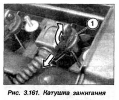
Unlock the ignition coil and disconnect it from the ignition coil (1, Fig. 3.161) and remove the coil with an upward movement.
Before installation, it is necessary to check the ignition coil by the shape of the multi-spark discharge signal using the "12.7.050" device and a DIS tester. The ignition oscillogram is shown in Fig. 3.162.
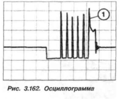
Depending on the engine temperature (20-100°C) and the shaft speed (2000 min⁻¹), several (1-5) initial voltage pulses are supplied before the normal ignition voltage, the first one being the decisive voltage pulse. Additional breakdown voltages do not play any role.
The ignition coil should be installed in the reverse order, while checking the integrity and position of the ignition coil rubber seal. After replacing the ignition coils, it is necessary to read the fault information from the memory of the ECU-KSUD of the "DME" system. Eliminate the faults and erase the fault information from the memory of the memory.