
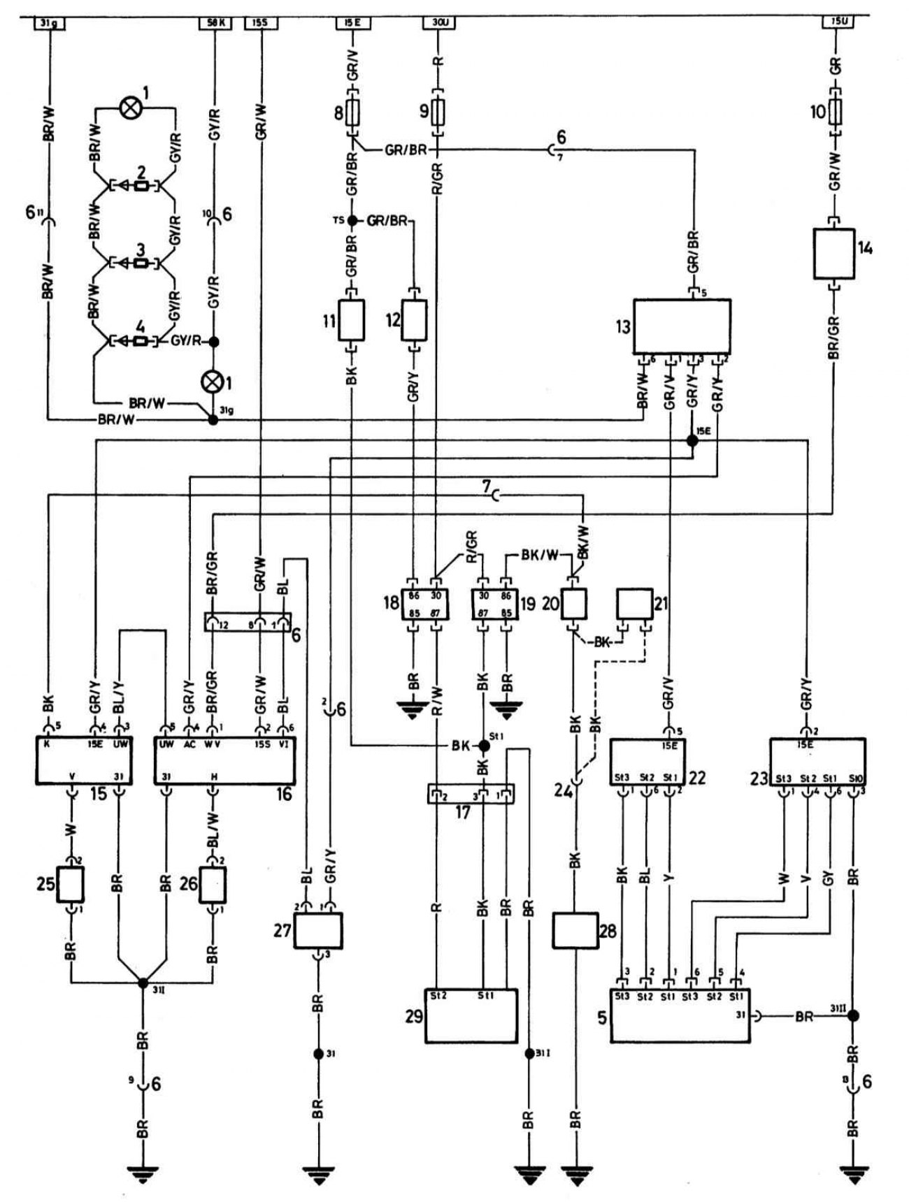
Schematic diagram of the heating and air conditioning system
Open large image in new tab »
1 — Backlight of heater control instruments
2 — LED 3
3 — LED 2
4 — LED 1
5 — Heater/evaporator blower switch
6 — Plug - heater control wiring to central wiring (13 contacts)
7 — Plug - front wiring section to heater controls
8 — Fuse - heater blower
9 - Fuse - additional fan stage 2
10 - Fuse - signal lamp, reverse signal lamps, tachometer and mirrors (power distributor)
11 - Temperature switch 91°C - stage 1
12 - Temperature switch 99°C - stage 2
13 — Air conditioning switch
14 - Water valve
15 — Evaporator temperature regulator
16 — Air conditioning control unit (heater controls)
17 — Plug - additional fan motor (on the additional fan motor)
18 — Relay - additional fan stage 2 (on the power distributor)
19 — Relay - additional fan stage 1 (on the power distributor)
20 — Switch - high pressure switch (dryer)
21 - Switch - temperature 110°C (only for 524 td)
22 — Heater blower motor
23 — Evaporator blower motor
24 — Plug - high pressure switch to electromagnetic clutch
25 — Evaporator temperature sensor (in the evaporator)
26 — Heater temperature sensor (in the heater)
27 — Internal temperature sensor (lower left trim panel)
28 - Electromagnetic clutch for compressor
29 — Additional fan motor