
Without air conditioning
Heating and ventilation control panel
1. Disconnect the negative cable from the battery.
2. Remove the audio system as described in chapter 12.
3. Pull the handles off the controls on the panel.
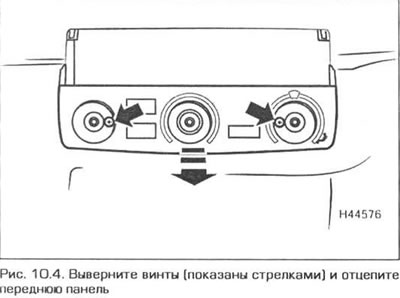
4. Remove the screws and unhook the front panel from the ventilation and heating control panel (pic. 10.4).
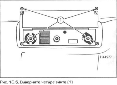
5. Unscrew the four screws securing the panel frame, release the panel from the latches, push the panel inward and remove the frame from the opening (pic. 10.5).
6. Disconnect the electrical connectors and unhook the cables from the controls. Mark the position of each cable and its routing to avoid assembly errors.
7. Installation of the panel is carried out in reverse order. Lay and connect the cables according to the marks made during disassembly. Before finally fixing the panel, check the operation of all controls
Heating and ventilation control cables
8. Remove the heating and ventilation control panel as indicated in p.p. 1-6 and disconnect the appropriate cable from the control.
9. On right-hand drive models, remove the screws, release from the clips and remove the lower facing of the front panel on the driver's side. On left-hand drive models, remove the glove box as directed in Chapter 11, paragraph 27.
10. Follow the route of the desired cable behind the front panel and disconnect the other end of the cable from the mixing chamber.
11. Install the new cable in reverse order. Then make sure that the cable is correctly laid, does not have sharp bends and is not twisted. Check the operation of the relevant control, then replace the control panel.
Heater radiator
12. At the rear of the engine compartment, remove the inlet air duct of the ventilation and heating system as follows.
- A) Turn 90 counter-clockwise the three retainers of the cabin filter cover and remove the cover Pull out the cabin filter.
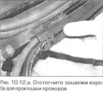
- b) Release the latches on the wiring box and remove the wiring from the box (pic. 10.12, a).
- V) Remove the four screws securing the cabin filter housing and pull the housing out.
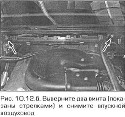
- G) Remove two screws (pic. 10.12, b) and pull the air duct up out of the engine compartment.
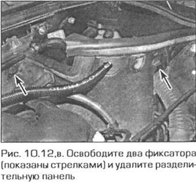
- d) If necessary, pull up the rubber seal in the left rear corner of the engine compartment, release the two latches and pull out the separation panel (pic. 10.12, in).
13. Turn away a stopper of a broad tank to equalize pressure in system of cooling with atmospheric, then again close a tank.
14. Clamp both heater hoses as close to the engine baffle as possible to reduce fluid loss. Alternatively, drain the coolant.
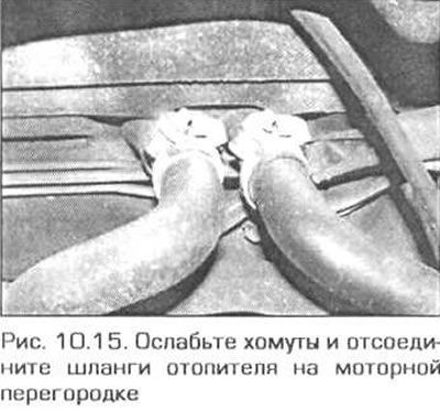
15. Disconnect the heater hoses on the engine bulkhead (pic. 10.15).
16. Remove the front panel as described in chapter 11.
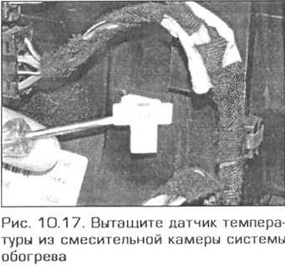
17. Remove the temperature sensor from the mixing chamber of the heating system (pic. 10.17). Release the wiring harness from the fasteners.
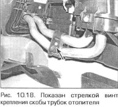
18. Pull out from a mixing chamber an air duct from outside of the passenger. Unscrew the screw of the bracket of the heater tubes, and remove the bracket (pic. 10.18).
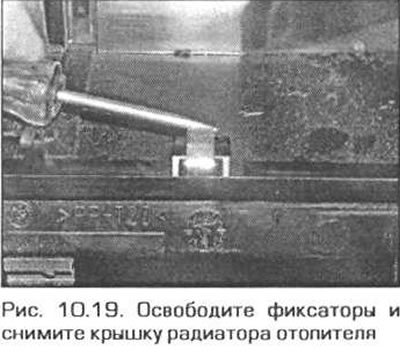
19. Release the clips and remove the heater radiator cover from the mixing chamber (pic. 10.19).
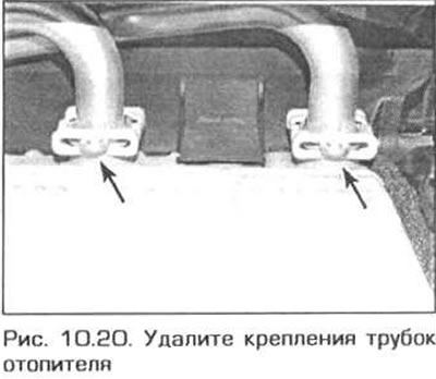
20. Remove the heater radiator tube fasteners, lift the tubes and pull the radiator out of the mixing chamber (pic. 10.20). Remove the o-rings from the tubes.
Note. Do not turn the radiator upside down so as not to drink the liquid. If fluid does spill, soak it up immediately with a rag and wipe the spilled area dry.
21. Installation is carried out in sequence. reverse withdrawal. Replace all o-rings. Finally, fill the cooling system with liquid.
Heater fan
22. Disconnect the negative battery cable. In the engine compartment, remove the inlet air duct of the heating and ventilation system (see point 12).
23. On a 6-cylinder engine, remove the plastic engine covers so that they do not interfere with the removal of the fan.
24. On all models, remove the rubber seal, remove the four screws, and remove the fan cover.
25. Turn out screws of fastening of the fan and lower it. Disconnect the fan wiring as soon as possible.
26. Installation of the fan is carried out in the reverse order. Attach the fan to the mixing chamber and cover the chamber with a lid.
Fan resistor
27. In the engine compartment, remove the inlet air duct of the heating and ventilation system, as indicated in paragraph 12.
28. On all models, remove the rubber seal, remove the four screws, and remove the fan cover.
29. Turn out the screw of fastening of the resistor, disconnect from it conducting and remove the resistor.
30. Installation is carried out in reverse order.
Heater radiator valve
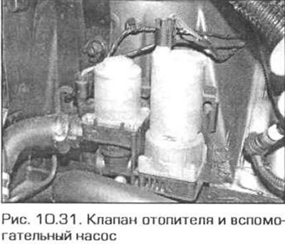
31. The coolant valve to the heater is installed on the left mudguard in the engine compartment. On some models, an auxiliary pump is located next to the valve (pic. 10.31). Unscrew the plug of the expansion bank to equalize the pressure in the cooling system with atmospheric pressure, then screw the plug back on.
32. Remove the air cleaner (see chapter 4A).
33. Clamp both heater hoses as close to the valve as possible to minimize fluid loss.
34. Disconnect the electrical wiring from the valve.
35. Loosen the clamps and disconnect the hoses from the valve, then disconnect the valve from the body and remove it from the engine compartment.
36. Valve installation is carried out in the reverse order.
Air conditioned
Control Panel
37. Pull up the shift knob sharply and remove it from the lever (mechanical transmission) or remove the selector lever (automatic transmission).
38. Remove the lining of the base of the gear lever (or selector). Then disconnect the electrical connectors.
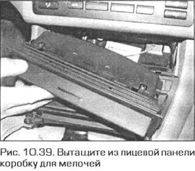
39. Pull out the box for small items under the heater control panel. Carefully pry up the bottom edge of the box, starting at the corner (pic. 10.39). If you are removing the cup holder, press lightly on the top wall of the box, push it back about 2 mm, then press the right and left edges of the box down and pull it out of the front panel.
40. Remove the four screws securing the box frame and pull the frame out of the front panel (pic. 10.40). Disconnect any electrical connectors that you have access to.
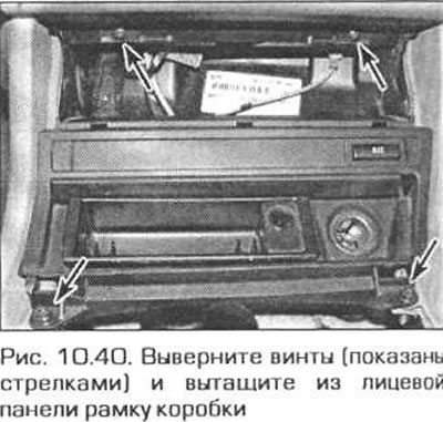
41. Press the heater control panel from the back and remove it from the front panel (pic. 10.41).
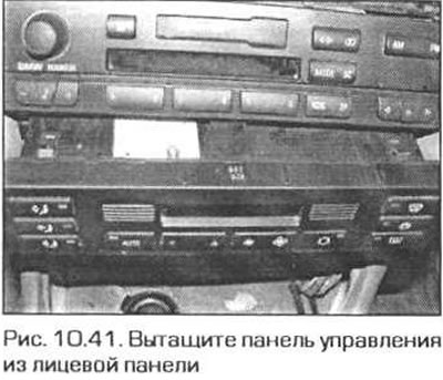
42. Disconnect the now accessible electrical connectors.
43. Installation is carried out in reverse order.
Heater radiator
44. Transfer the car to a specialized service station to discharge the air conditioning system.
45. Remove the front panel as described in chapter 11.
46. Remove the inlet air duct of the system in the engine compartment, as indicated in paragraph 12.
47. Clamp the heater hoses as close to the engine baffle as possible to minimize fluid loss. Alternatively, drain the coolant.
48. Loosen the heater hose clamps on the engine bulkhead and disconnect the hoses.
49. Turn out bolts of fastening of tubes of the conditioner on a motor partition. Tubing seals can be discarded - new ones are required for reassembly.
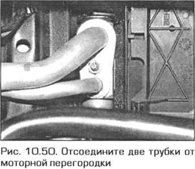
50. Remove the bolt securing the two pipes of the air conditioning system to the engine bulkhead and move the pipes to the side (pic. 10.50). Seals can be discarded - new ones will be needed for assembly.
51. Remove the four screws from the engine bulkhead on the side of the engine compartment (see fig. 12.7, a, b).
52. Remove the steering column (see chapter 10)
53. Turn out bolts and remove all arms of fastening of the mixing chamber of the central air, separate all electric sockets and remove the chamber.
54. Get ready for a coolant leak and place a suitable container under the heater radiator pipes.
55. Follow the steps described in paragraphs 17-20.
56. Installation is performed in sequence. reverse withdrawal. Replace all O-rings upon reassembly. Finally, fill the cooling system. Transfer the car to a specialized service station for refueling the air conditioner.
Heater fan
57. Remove the inlet air duct of the interior ventilation system, as described in paragraph 12. On models with a 6-cylinder engine and left-hand drive, remove the cylinder head cover (see chapter 2A or 2B).
58. Separate the rubber sealing strip from the air path inlet.
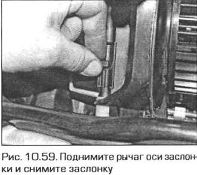
59. Pull up the left damper axle lever and remove the damper (pic. 10.59).
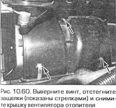
60. Remove one screw, unfasten the latches and remove the front fan cover (pic. 10.60).
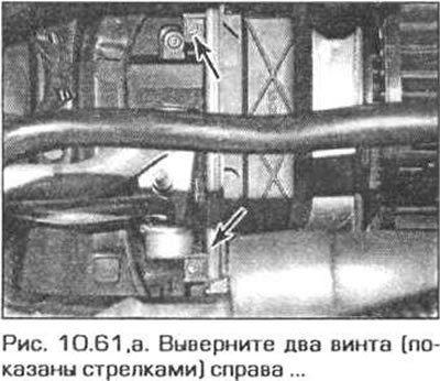
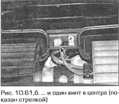
61. Remove the three screws and remove the right cover from the fan (pic. 10.61, a, b).
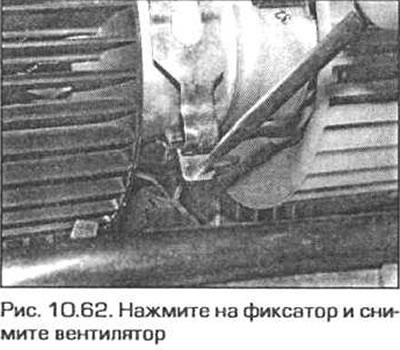
62. Disconnect the fan motor electrical connector, press the tab with a long thin tool and remove the fan (pic. 10.62). Pull the fan out through the opening on the passenger side.
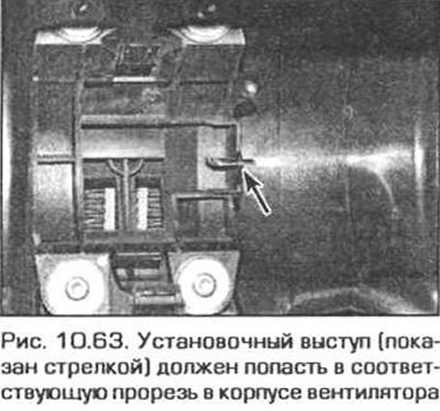
63. Installation is carried out in the reverse order of removal. The mounting protrusion on the mixing chamber housing must fit into the rectangular hole in the fan housing (pic. 10.63).
Fan resistor
64. See paragraph 12, subheading Fan speed limiter.
Heater radiator valve
65 See paras. 31-36.