
- Home
- BMW 3 Series
- E46
- Power unit
- Cooling and heating
- Air conditioning system components — removal and installation
Air conditioning system components — removal and installation (BMW 3 Series E46)
Warning! Do not attempt to disconnect the air conditioning system circuit yourself. Observe the precautions specified in paragraph 11.
Evaporator
Removal
1. Take the vehicle to a specialized service station to have the refrigerant removed.
2. Remove the heater radiator as described in paragraph 10.
3. Remove the steering column (see chapter 10).
4. At the rear of the engine compartment, remove the ventilation and heating system air inlet duct as follows.
- a) Turn the three cabin filter cover fasteners 90° counterclockwise and remove the cover. Pull out the cabin filter.
- b) Unfasten the clips of the box for laying the wires and remove the wiring from the box (see fig. 10.12,a)
- c) Unscrew the four screws securing the cabin filter housing and pull the housing out.
- d) Remove two screws (see fig. 10.12,b) and pull the air duct up out of the engine compartment.
- d) If necessary, pull up the rubber seal in the left rear corner of the engine compartment, release the two clips and pull out the partition panel.
5. Disconnect all wires from the front panel cross member. Unscrew the corresponding bolts and remove the cross member.
6. Disconnect the air conditioning pipes at the engine bulkhead. The sealing rings of the connections can be discarded - new ones will be required during assembly.
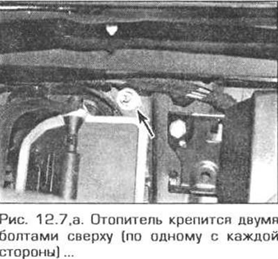
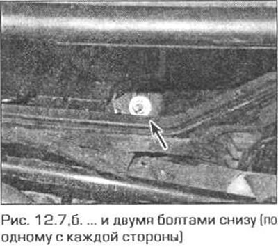
7. Unscrew the bolts securing the heater to the engine bulkhead (fig. 12.7,a,b).
8. Remove the fan speed limiter (see below in this paragraph).
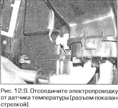
9. Disconnect the electrical wiring from the temperature sensor and remove the sensor from the evaporator (Fig. 12.9).
10. Disconnect the drive from the servomotor, disconnect all electrical connectors and release all wires from their fasteners.
11. Release the clips from the bottom of the evaporator and remove the evaporator.
Note: Do not damage the evaporator fins. Straighten any bent fins if necessary.
12. Install the evaporator in the reverse order. Entrust the filling of the system with refrigerant to service station specialists. Fill the cooling system.
Expansion valve
13. Take the vehicle to a specialized service station to have the refrigerant removed.
14. At the rear of the engine compartment, remove the ventilation and heating system air inlet duct as follows.
- a) Turn the three locks of the cabin filter cover 90° counterclockwise and remove the cover. Pull out the cabin filter.
- b) Unfasten the latches of the box for laying the wires and remove the wiring from the box (see fig. 10.12.a).
- c) Unscrew the four screws securing the cabin filter housing and pull the housing out.
- d) Pull up the rubber seal in the left rear corner of the engine compartment, release the two clips and move the partition panel forward a little.
- d) Remove two screws (see fig. 10.12,6) and pull the air duct up out of the engine compartment.
15. Remove the two screws and the air conditioning supply and return lines from the engine bulkhead. The sealing rings can be discarded - new ones will be required for reassembly
16. Raise the axle lever and remove the air recirculation flap (see fig. 10.59).
17. Unscrew the bolt securing the two air conditioning system pipes to the engine bulkhead and move the pipes to the side (see fig. 10.50).
18. Remove the two screws and the expansion valve. The sealing rings can be discarded - new ones will be required for reassembly.
19. Install the valve in the reverse order. Entrust the filling of the system with refrigerant to service station specialists. Add liquid to the cooling system to the required level.
Receiver with dryer
20. The receiver requires replacement in the following cases.
- a) Dirt has entered the air conditioning system.
- 6) When replacing the compressor.
- c) When replacing the condenser or evaporator.
- d) The refrigerant has leaked out of the system.
- d) The air conditioning system was left open for more than 24 hours.
21. Take the vehicle to a specialized service station to have the refrigerant removed.
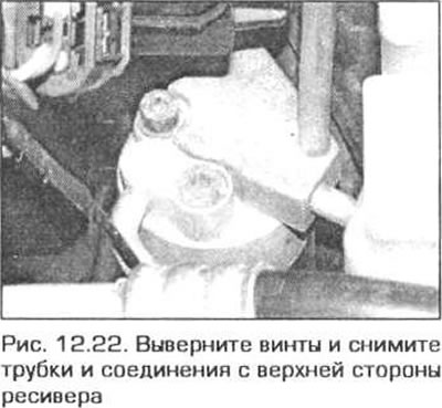
22. The receiver is located in the right corner of the engine compartment. Remove the screws and remove the tubes and connections from the top of the receiver (fig. 12.22). The sealing rings can be discarded - new ones will be required for assembly.
Note: If the desiccant will be left open for more than an hour, plug the opening with a stopper.
23. Remove the right front fender poker (see paragraph 23 of chapter 11).
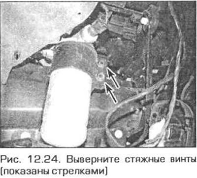
24. Loosen the clamping screws and pull the receiver out of the clamp (fig. 12.24).
Compressor
25. Take the vehicle to a specialized service station to have the refrigerant removed.
26. Apply the parking brake, raise the front of the car and place it on reliable stands. Remove the mudguard from under the engine.
27. Remove the accessory drive belt.
28. On the model with the 4-cylinder N42 engine, remove the air cleaner (see chapter 4A).
29. On the 6-cylinder model, release the washer bottle and move it to the side.
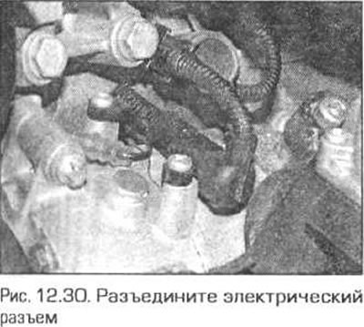
30. On all models, disconnect the compressor electrical connector (fig. 12.30).
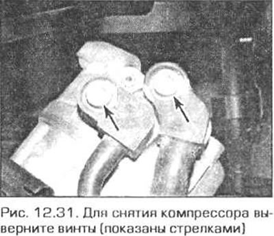
31. Disconnect the tubes from the compressor (Fig. 12.31). The sealing rings can be discarded - new ones will be required for assembly.
32. Unscrew the three compressor mounting bolts from under the vehicle and remove it from the vehicle.
33. Installation of the compressor is carried out in the reverse order, taking into account the following notes.
- a) Before installing the compressor, fill it with the required amount of special oil for cooling systems.
- b) Always replace the sealing rings when connecting air conditioner pipes.
- c) Entrust filling the system with refrigerant to service station specialists.
Pressure sensor
34. The pressure sensor is installed on top of the receiver. Take the car to a specialized service station to have the refrigerant removed.
35. Disconnect the electrical connector plug from the sensor and unscrew the sensor.
36. Install the sensor in the reverse order of removal. Tighten it securely. Leave the system filling with refrigerant to service station specialists.
Condenser
37. Take the vehicle to a specialized service station to have the refrigerant removed.
38. The condenser is located in front of the radiator of the cooling system. Remove the radiator as described in paragraph 3.
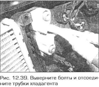
39. Disconnect the refrigerant pipes from the condenser (fig. 12.39). The sealing rings can be thrown away - new ones are needed for assembly.
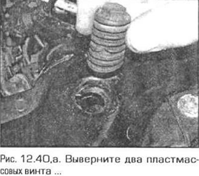
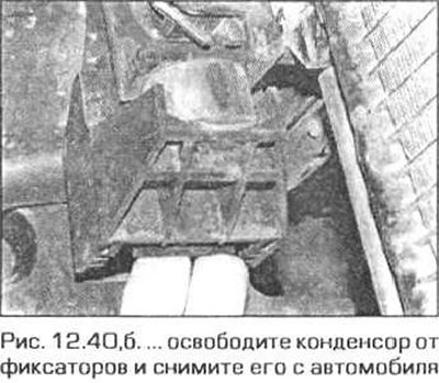
40. Remove the two plastic screws that secure the condenser through the crossbar. Lift the condenser up and away from the support bracket (fig. 12.40,a, b).
41. The condenser is installed in the reverse order, taking into account the following points.
- a) Before installing the condenser, add the required amount of air conditioning oil.
- b) Replace all sealing rings in the connections.
- c) Entrust filling the system with refrigerant to service station specialists.
Fan speed limiter
42. Disconnect the right passenger footwell air duct from the mixing chamber.
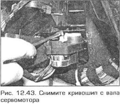
43. Carefully remove the crank from the servo motor shaft. Remove the two screws (one on top and one on the bottom) and remove the bracket and servo motor (fig. 12.43).
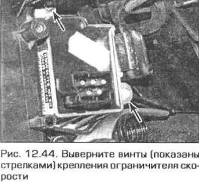
44. Disconnect the electrical connector from the limiter, unscrew the two mounting screws and remove the limiter (fig. 12.44).
45. Installation is carried out in reverse order.
This article is available at russian, bulgarian, belarusian, ukrainian, serbian, croatian, romanian, polish, slovak, hungarian
Article verified: Ilyinsky Matvey
Share information:
Previous articles
БМВ E46: Cooling and heating
Next articles
Similar articles on other types of BMW cars:
Removal and installation the injection pump of the Kugelfischer system BMW 5 Series E12 (1972-1981)
Removal and installation the actuator motor/microswitch of the… BMW 5 Series E39 (1995-2003)
Exhaust system components — removal and installation BMW 7 Series E32 (1986-1994)
Removal other components of the air conditioning system BMW 7 Series E38 (1994-2001)
Removal and installation the airbag system module in the left or… BMW X3 E83 (2003-2010)
Removal and installation the engine BMW X5 E53 (1999-2006)
Link in different formats to this page
Visitor comments
No comments yet
- General information
- Manual
- Maintenance
- Power unit
- Engine repair
- Cooling system
- Power system (gasoline)
- Injection system (gasoline)
- Fuel system (diesel)
- Exhaust system
- Ignition system
- Charge and launch systems
- Transmission
- Car gearbox
- Clutch and drive shafts
- Chassis
- Brake system
- Suspension front and rear
- Steering
- Body
- Body care and repair
- Exterior
- Interior
- Electrical equipment
- Troubleshooting
- Lighting and signaling
- Equipment and devices
- Heater and air conditioner
- Electrical circuits
- General information
- Manual
- Repair on the road
- Weekly checks
- Maintenance
- Troubleshooting
- Power unit
- 4 cylinder engines
- 6 cylinder engines
- Engine overhaul
- Cooling and heating
- Fuel and exhaust system
- Starting and charging system
- Ignition system
- Transmission
- Clutch
- Mechanical gearbox
- Automatic gearbox
- Cardan and drive shafts
- Chassis
- Brake system
- Wheel suspension
- Steering
- Body
- Exterior
- Interior
- Electrical equipment
- Equipment and devices
- Electrical circuits
- General information
- Maintenance
- Power unit
- Engine repair
- Cooling system
- Ignition system
- Supply system
- Fuel injection system
- Exhaust system
- Transmission
- Clutch
- Car gearbox
- Front and rear axle
- Chassis
- Steering
- Brake system
- Body
- Exterior
- Interior
- Electrical equipment
- Heating system
- Equipment and devices
- Power devices
- Electrical circuits
- Power unit
- M10/M20 engine
- M40 engine
- Ignition system
- Lubrication system
- Cooling system
- Supply system
- Fuel injection
- Exhaust system
- Transmission
- Clutch
- Manual gearbox
- Front axle
- Rear axle
- Chassis
- Steering
- Brake system
- Body
- Exterior
- Interior
- Electrical equipment
- Heating system
- Equipment and devices
- Electrical circuits
- General information
- Specifications
- Operation and maintenance
- 4-cylinder engine
- Engine repair
- Cooling and lubrication system
- Supply system
- Ignition system
- 6-cylinder engine
- Engine repair
- Cooling and lubrication system
- Supply system
- Fuel injection system
- Ignition system
- Transmission
- Clutch
- 4-speed manual gearbox
- 5-speed manual gearbox
- Automatic gearbox
- Cardan and rear axle
- Chassis
- Steering
- Front suspension
- Rear suspension
- Brake system
- Electrical equipment
- Equipment and devices
- Electrical circuits