
Attention! Disconnecting the ground wire with the ignition on causes the ECU-KSUD to fail. Disconnect only with the ignition off. When disconnecting the negative terminal from the battery, the ECU fault codes, anti-theft system codes and individual audio equipment settings are erased from the ECU memory. When installing the cooling system, replace the tape clamps, if they were installed, by cutting them off with side cutters and using screw clamps.
Note: Before disconnecting and removing the components, mark them with tags or adhesive tape. Record the locations of the units and parts to be removed on the engine compartment plan.
Prepare your work area before starting work (stand or workbench and rack), devices ("11.0.000", "51.2.170" and "00.0.200"), garage jack, jack stands (goats, stands) and a lifting device such as a crane (hoist). Prepare a protective cover or thick fabric material to cover the surface of the engine compartment wings of the body when performing work. The engine should be removed from the car - upwards. With the gearbox disconnected and the hood fixed in the upper position.
The engine must be removed in the following order. Place the vehicle on a ramp, overpass, lift, inspection pit or level surface using stands. Apply the parking brake. Read the readings from the KSUD diagnostic SHR. Turn off the ignition and disconnect the "-" terminal from the battery, insulate the terminal. Fix the hood on the body in the open position using the "51.2.170" device.
Device "51.2.70"
Relieve pressure in the fuel lines, disconnect the pipeline from the distribution line and plug the ends of the pipes/hoses with plugs or clamps.
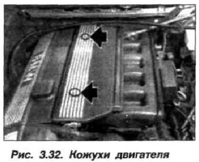
Remove the plugs (arrows, see Fig. 3.32) and unscrew the bolts, remove the protective covers from the engine.
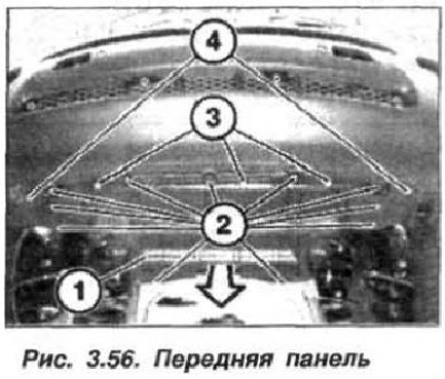
Loosen the bolts (1 and 2, Fig. 3.56) and remove the front panel (3) of the engine auxiliary mechanism protection.
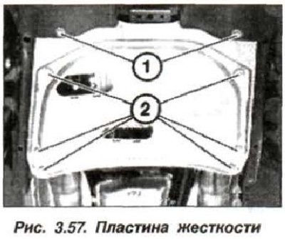
Loosen the bolts (1, Fig. 3.57) fastening the stiffening plate at the front, then the bolts (2) at the rear and remove the stiffening plate.
Disconnect the oxygen sensors from the exhaust gas oxygen sensors.
Disconnect the oil lines from the automatic transmission heat exchanger and remove. Plug the holes with plugs. Take measures to prevent the engine from tipping over after removing the gearbox and remove it. Remove the air filter housing.
Remove the air conditioning compressor drive belt. Remove the air conditioning compressor from the support bracket, move it to the side and secure it to the body with a wire clip. Leave the pipes connected.
Drain the coolant, the drain plug for the coolant from the cylinder block is located on the exhaust side, in the area of the second cylinder. The drained coolant is subject to disposal.
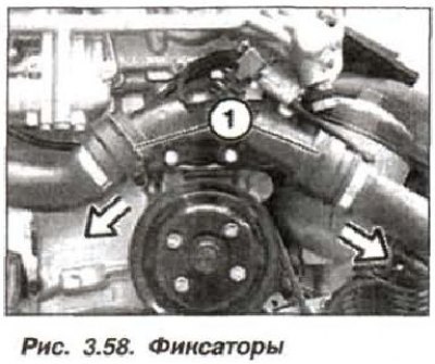
Remove the clamps (1, Fig. 3.58) and disconnect the hoses (arrows) from the thermostat housing.
Remove the engine cooling system radiator. Remove the intake manifold. Disconnect the hoses from the cooling system pipes and from the heater valve block.
Disconnect the engine wiring harness SS on the control unit and disconnect it. Unlock the ignition coil wiring harness branch on the control unit and disconnect it. The wiring harnesses remain on the engine. Disconnect the "+" wire from the battery terminal.
Remove both oxygen sensors. Disconnect the vacuum line from the brake booster. Unlock and disconnect the wire from the fuel tank ventilation valve.
Pump out the liquid from the tank (reservoir) power steering pump, send the fluid for disposal. Unscrew the bolts (Fig. 3.59) securing the tank, move it to the side and secure it to the body with a wire clamp.
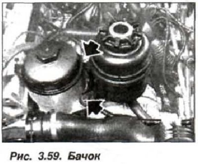
Leave the pipelines connected.
Remove the fan impeller from the coolant pump together with the fan drive viscous coupling. Remove the alternator drive belt. Remove the power steering pump, move it to the side and secure it with a wire clamp to the body. Leave the pipes connected.
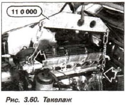
Install the lifting rigging, device "11.0.000" (Fig. 3.60), on the engine lifting eyes and tighten it slightly with a hoist.
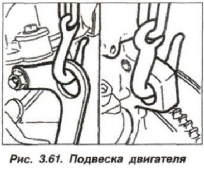
The location of the front and rear lugs for removing the engine is shown in Fig. 3.61.
Support the engine with a wooden block secured to the front axle cross member.
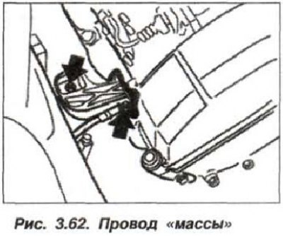
Disconnect the ground wire (Fig. 3.62) located on the right side of the engine.
Loosen the nuts securing the left and right engine mount cushions (left arrow). Disconnect the exhaust pipes from the engine exhaust manifolds.
Make sure that all hoses and wiring harnesses connecting the engine to the body are disconnected.
Smoothly lift the engine with a hoist (crane) and remove the engine from the compartment, making sure not to damage adjacent structures if they are accidentally touched. Install the engine on a disassembly stand or on a workbench.
Attention! The engine must be kept in a vertical position at all times, which ensures the preservation of oil in the hydraulic tappet cylinders. If it is necessary to turn the engine over, the hydraulic tappets must first be removed or the engine must be turned for no more than 5 minutes. When disconnecting the hydraulic drive elements, air gets into the system. After assembling the system, it must be bled to remove air.
The engine installation should be carried out in the reverse order, while it is necessary to check the engine mounts, coolant, oil and fuel hoses for porosity, delamination and cracks. If defects are found, replace the parts with new ones.
Check for the presence of the centering sleeve for connecting the engine to the gearbox. Smoothly lower the engine onto its supports. Install new self-locking nuts on the engine supports by hand, but do not tighten them completely. Install the gearbox. Tighten the engine and gearbox connection bolts to the following torque, unless otherwise specified:
- bolts M8—25 N·m (2.5 kgf·m);
- bolts M10—45 N·m (4.5 kgf·m);
- bolts M12—60 N·m (6.0 kgf·m).
Lower the vehicle onto its wheels. Using strong shaking movements, position the engine and tighten the engine mount nuts to the body to a torque of 42 N·m (4.2 kgf·m). Tighten the bolts connecting the exhaust manifolds to the exhaust system to a torque of 15 N·m (1.5 kgf·m).
Tighten the air conditioning compressor and power steering pump connecting bolts to the following torque:
- compressor bolt M8 25 Nm (2.5 kgf·m);
- compressor bolt M10 30 Nm (3.0 kgf·m);
- pump bolts 20 Nm (2.0 kgf·m).
Install the alternator, coolant pump, power steering pump and air conditioning compressor drive belts.
Restore all electrical connections, joining the joints. Install the intake manifold. Restore all hydraulic and pneumatic connections.
Replace the cylinder block drain plug sealing ring and tighten the plug (M 14x1.5) to 25 N·m (2.5 kgf·m). Check the oil level in the engine and automatic transmission, antifreeze in the cooling system and the working fluid in the power steering.
Start and warm up the engine, check the tightness of the systems. Recheck the oil and antifreeze levels. Check the engine crankshaft speed at idle and the CO content in the exhaust gases.
Install the engine bay stiffening plate. Be sure to install the spacer washers. The tightening torque of the new mounting bolts consists of two steps - a torque of 5.6 kgf·m (56 N·m) + an additional turn of 90°. Install the engine auxiliary mechanism protection panel.