
- Home
- BMW X5
- E53
- M54 petrol engine
- Engine repair
- Piston group — design description
Piston group — design description (BMW X5 E53)
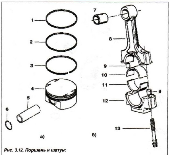
1, 2 - compression ring; 3 - oil scraper ring; 4 - piston; 5 - piston pin; in - retaining ring (∅ 22x1.5); 7 - Upper head bushing; 8 - connecting rod; 9 - centering sleeve; 10 - insert (blue); 11 - insert (red); 12 - connecting rod cover; 13 - connecting rod bolt (47 mm)
Piston
The pistons are installed on the engine (fig. 3.12,a) from the company "Mahle" made of aluminum alloy with steel inserts.
Each piston has two compression rings and one oil scraper ring. For correct orientation of the piston when installed in the cylinder, there is an arrow on its bottom, which should face the camshaft drive, as well as a mark indicating its diameter. The piston diameter is measured at a distance of 8 mm from the lower edge of the piston skirt at an angle of 90° relative to the axis of the piston pin.
| B22 | B25/B30 | |
| Piston diameter, mm | ||
nominal | 79,980 | 83.995 |
intermediate | 79,993 | 84.009 |
1st repair size | 80,230— 80,243 | 84,235— 84,259 |
| Calculated clearance between piston and cylinder for new parts | from 0.01 to +0.04 | |
max. allowed. | 0,15 | |
| Permissible weight difference between pistons for one engine, g. | 10,0 | |
Piston pins
Piston pin (fig. 3.12, 5) steel, ground, floating type.
It is held from axial movement by two retaining rings in the piston holes for the piston pin. The pins are made in two classes, marked with color marks - black and white.
The engine piston pin diameter is 22 mm, with a manufacturing tolerance of -0.003 to -0.006 mm.
The nominal clearance between the piston pin and the piston is 0.001-0.005 mm. The clearance between the piston pin and the connecting rod upper head bushing:
- fingers with a "white" mark - 0.005-0.013 mm;
- fingers with a "black" mark - 0.008-0.015 mm.
Piston rings
The piston rings are installed in the grooves of the piston head: two compression rings (1,2) and one oil scraper ring (3).
The rings are installed on the piston with the mark "Top" ("Top") towards the bottom of the piston (fire belt). The upper compression ring is chrome-plated, with rounded edges, the lower compression ring is conical, the oil scraper ring has an expander.
Clearance between new piston ring and groove wall:
- upper compression 0.020-0.060 mm;
- lower compression 0.020-0.060 mm;
- oil scraper 0.020-0.060 mm;
- maximum permissible 0.12 mm.
Break gap of new piston ring:
- upper compression 0.10-0.30 mm;
- lower compression 0.20-0.40 mm;
- oil scraper 0.20-0.60 mm.
The maximum permissible gap in the lock for all engine models for compression rings is 0.80 mm, oil scraper rings 1.00 mm.
Connecting rods
Connecting rods (8. Fig. 3.12,b) forged, with an I-section rod made of heat-treated steel, with thin-walled trimetallic bearing liners (10, 11).
A bimetallic, collapsible part is pressed into the upper head of the connecting rod (rolled up) bushing (7).
According to the diameter of the lower head hole, the connecting rods are divided into two size groups, marked with color marks of red and blue.
Connecting rod lower head bore diameter:
- with red mark 48.000—48.008 mm;
- with blue mark 48.009—48.016 mm.
The lower connecting rod head undergoes final processing with its cover (12) and is not subject to further disassembly.
Connecting rod upper head bushing diameter:
- outer 24.060—24.100 mm;
- internal 22.011—22.005 mm;
The diameter of the lower connecting rod head, without bearing, is 48.000–48.016 mm.
The maximum permissible operating clearance between the connecting rod bearings and the crankshaft journals for all engine models is 0.12 mm. The permissible difference in weight between connecting rods on one engine is no more than 4.0 g.
The permissible twisting of the connecting rod for all engine models is no more than 30'. The tolerance of non-parallelism and skew of the axes of the holes over a length of 100 mm, for all engine models, is no more than 0.04 mm. The maximum axial clearance of the connecting rod on the crankshaft journal relative to its cheek for all engine models is no more than 0.37 mm.
This article is available at russian, bulgarian, belarusian, ukrainian, serbian, croatian, romanian, polish, slovak, hungarian
Article verified: Zhuravleva Isolda
Share information:
Previous articles
БМВ E53: Engine repair
Next articles
Similar articles on other types of BMW cars:
Disassembling the connecting rod and piston group BMW 3 Series E21 (1975-1983)
Clutch: general information and design BMW 3 Series E36 (1990-2000)
Disassembly and assembly of the connecting rod and piston group BMW 5 Series E12 (1972-1981)
The design of engines M20, M50, M30, M21, M51 BMW 5 Series E34 (1988-1996)
General description of the car BMW 7 Series E32 (1986-1994)
Fuses — general description BMW X3 E83 (2003-2010)
Link in different formats to this page
Visitor comments
No comments yet
- General information
- Manual
- Maintenance
- M54 petrol engine
- Engine repair
- Lubrication system
- Cooling system
- Supply system
- Injection system
- Exhaust system
- Engine electrics
- M62 petrol engine
- Engine repair
- Lubrication system
- Cooling system
- Supply system
- Exhaust system
- Engine electrics
- N62 petrol engine
- Engine repair
- Cooling and lubrication system
- Power and exhaust system
- Engine electrics
- Diesel engine M57
- Engine repair
- Lubrication system
- Cooling system
- Power and exhaust system
- Engine electrics
- Turbocharging system
- Transmission
- Clutch
- Mechanical gearbox
- Automatic gearbox
- Transfer case and cardan
- Chassis
- Brake system
- Steering
- Front suspension
- Rear suspension
- Wheels and tires
- Body
- Exterior
- Interior
- Doors and windows
- Repair and maintenance
- Heater and air conditioner
- Electrical equipment
- Equipment and devices
- Levers and switches
- Electrical circuits