
Table of contents: Checking the technical condition of…↓ Assembly of the connecting rod and…↓
- Home
- BMW 5 Series
- E12
- Power unit
- Engine repair
- Disassembly and assembly of the connecting rod and piston group
Disassembly and assembly of the connecting rod and piston group (BMW 5 Series E12)
The piston pins rotate freely in the upper head of the connecting rod and the piston bosses. The pin is held in the piston bosses from longitudinal movement by two retaining rings inserted into the annular grooves of the bosses.
Remove the piston rings.
Remove the pin retaining rings from the ring grooves of the bosses using a scriber.
Clamp the connecting rod vertically in a vice with soft pads and use a mandrel of the appropriate size to press out the piston pin.
Installation clearances, permissible wear and grinding limits are specified in the subsection "Detailed technical specifications".
All operations for checking and repairing the cylinder head are described in at the beginning of this section.
Make sure that the connecting rods are in the same weight group: connecting rods without bearing shells should not differ from each other in weight by more than ±4 g. Check for color markings of weight groups on the connecting rods. If there are no markings, compare the connecting rods by weight, using one of them as a reference.
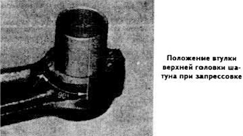
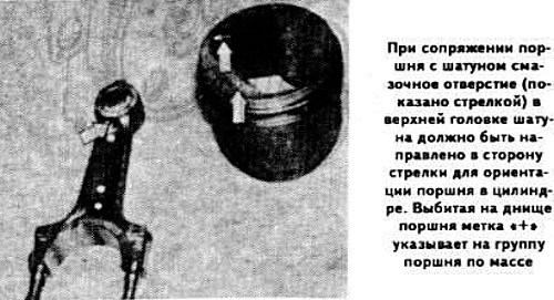
Check the condition of the connecting rod upper head bushings. When replacing the connecting rod upper head bushing, it is necessary to align the lubrication holes in the bushing and the connecting rod head. To do this, it is necessary to shift the bushing lock by 90° relative to the hole in the connecting rod upper head (see photo).
The upper connecting rod head bushings are bored at the factory to exactly the outside diameter of the piston pins. However, the pin should be checked for proper fit to the bushing. For proper mating, the piston pin, lightly lubricated with animal fat or motor oil, should fit into the bushing hole with a simple push of the thumb. If necessary, bore the hole in the connecting rod bushing.
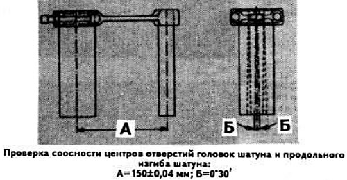
Check the alignment of the connecting rod head bore centers and the longitudinal bending of the connecting rod (see the figure and values in the subsection "Detailed technical specifications").
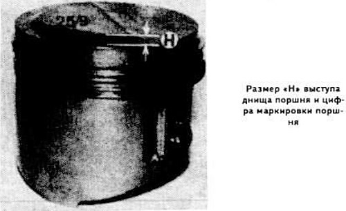
Make sure that the pistons belong to the same weight group, which is marked with "+" or "-" marks on the piston crown.
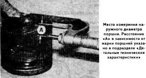
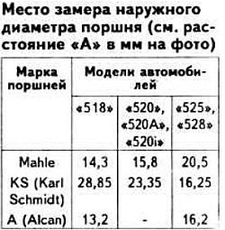
Check the clearance between the piston and the cylinder (see the value in the subsection "Detailed technical specifications") by measuring the outer diameter of the piston at a distance "A" from the piston skirt (see photo).
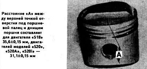
On models "518" and "520", also check the distance between the top of the piston pin hole and the bottom of the piston (see photo).
Install the retaining ring into the annular groove of the piston boss on the side opposite the arrow for orienting the piston in the cylinder, stamped on the piston bottom.
Clamp the connecting rod vertically in a vice with soft jaws, pointing the oil hole in the small end of the connecting rod towards you.
Lubricate the connecting rod bushing and piston bosses with engine oil.
Place the piston on the connecting rod, pointing the arrow towards you to orient the piston in the cylinder. Insert the piston pin into the piston hole until it stops against the installed retaining ring.
Install the second snap ring into the piston boss ring groove.
Assemble the other pistons with the connecting rods in the same way, install the connecting rod liners and connecting rod caps. Temporarily tighten the connecting rod bolts.
Since the 1978 model year, the meaning of dimensions "A" has changed (see the meanings in the subsection "Detailed technical specifications").
[This article is based on information from the website «BMWMan»]
Remove the piston rings.
Remove the pin retaining rings from the ring grooves of the bosses using a scriber.
Clamp the connecting rod vertically in a vice with soft pads and use a mandrel of the appropriate size to press out the piston pin.
Checking the technical condition of parts
Installation clearances, permissible wear and grinding limits are specified in the subsection "Detailed technical specifications".
All operations for checking and repairing the cylinder head are described in at the beginning of this section.
Assembly of the connecting rod and piston group
Make sure that the connecting rods are in the same weight group: connecting rods without bearing shells should not differ from each other in weight by more than ±4 g. Check for color markings of weight groups on the connecting rods. If there are no markings, compare the connecting rods by weight, using one of them as a reference.
Check the condition of the connecting rod upper head bushings. When replacing the connecting rod upper head bushing, it is necessary to align the lubrication holes in the bushing and the connecting rod head. To do this, it is necessary to shift the bushing lock by 90° relative to the hole in the connecting rod upper head (see photo).
The upper connecting rod head bushings are bored at the factory to exactly the outside diameter of the piston pins. However, the pin should be checked for proper fit to the bushing. For proper mating, the piston pin, lightly lubricated with animal fat or motor oil, should fit into the bushing hole with a simple push of the thumb. If necessary, bore the hole in the connecting rod bushing.
Check the alignment of the connecting rod head bore centers and the longitudinal bending of the connecting rod (see the figure and values in the subsection "Detailed technical specifications").
Make sure that the pistons belong to the same weight group, which is marked with "+" or "-" marks on the piston crown.
Check the clearance between the piston and the cylinder (see the value in the subsection "Detailed technical specifications") by measuring the outer diameter of the piston at a distance "A" from the piston skirt (see photo).
On models "518" and "520", also check the distance between the top of the piston pin hole and the bottom of the piston (see photo).
Install the retaining ring into the annular groove of the piston boss on the side opposite the arrow for orienting the piston in the cylinder, stamped on the piston bottom.
Clamp the connecting rod vertically in a vice with soft jaws, pointing the oil hole in the small end of the connecting rod towards you.
Lubricate the connecting rod bushing and piston bosses with engine oil.
Place the piston on the connecting rod, pointing the arrow towards you to orient the piston in the cylinder. Insert the piston pin into the piston hole until it stops against the installed retaining ring.
Install the second snap ring into the piston boss ring groove.
Assemble the other pistons with the connecting rods in the same way, install the connecting rod liners and connecting rod caps. Temporarily tighten the connecting rod bolts.
Since the 1978 model year, the meaning of dimensions "A" has changed (see the meanings in the subsection "Detailed technical specifications").
[This article is based on information from the website «BMWMan»]
This article is available at russian, bulgarian, belarusian, ukrainian, serbian, croatian, romanian, polish, slovak, hungarian
Article verified: Polikarpov Saveliy
Share information:
Previous articles
БМВ E12: Engine repair
Next articles
Similar articles on other types of BMW cars:
Disassembling the connecting rod and piston group BMW 3 Series E21 (1975-1983)
Engine overhaul — sequence of disassembly and assembly BMW 7 Series E32 (1986-1994)
Removal and installation, disassembly and assembly of suspension strut BMW 7 Series E38 (1994-2001)
Connecting electrical appliances BMW X3 E83 (2003-2010)
Piston group — design description BMW X5 E53 (1999-2006)
Link in different formats to this page
Visitor comments
No comments yet
- General information
- Governing bodies
- Manual
- Maintenance
- Power unit
- Engine repair
- Lubrication system
- Cooling system
- Ignition system
- Supply system
- Injection system (gasoline)
- Injection system (diesel)
- Exhaust system
- Transmission
- Clutch
- Car gearbox
- Front axle
- Rear axle
- Chassis
- Steering
- Brake system
- Wheels and tires
- Body
- Interior
- Exterior
- Heating system
- Electrical equipment
- Equipment and devices
- Power devices
- Windscreen wipers
- Electrical circuits
- General information
- Manual
- Maintenance
- Power unit
- Engine repair
- Ignition system
- Engine lubrication system
- Cooling system
- Fuel system (gasoline)
- Fuel system (diesel)
- Exhaust system
- Transmission
- Clutch
- Car gearbox
- Chassis
- Front and rear suspension
- Steering
- Brake system
- Body
- Exterior
- Interior
- Electrical equipment
- Heating system
- Equipment and devices
- Power devices
- Electrical circuits
- General information
- Manual
- Maintenance
- Power unit
- Engine in a car
- Engine overhaul
- Cooling system
- Supply system
- Ignition system
- Control system
- Transmission
- Clutch
- Manual gearbox
- Automatic gearbox
- Transmission line
- Chassis
- Steering
- Front suspension
- Rear suspension
- Brake system
- Body
- Body elements
- Car care and painting
- Electrical equipment
- Heater and air conditioner
- Equipment and devices
- Starter and generator
- Electrical circuits
- General information
- Operation and maintenance
- Specifications
- Power unit
- Engine repair
- Cooling and lubrication system
- Supply system
- Ecotronic power supply system
- Fuel injection system
- Ignition system
- Transmission
- Clutch
- Gearbox BMW 242/4
- Gearbox Getrag 262/8
- Gearbox Getrag 265/6
- Automatic gearbox
- Cardan gear
- Rear axle
- Chassis
- Steering
- Front suspension
- Rear suspension
- Brake system
- Electrical equipment
- Equipment and devices
- Electrical circuits