
Table of contents: Removal and installation ↓ Disassembly and assembly ↓
- Home
- BMW 7 Series
- E38
- Chassis
- Front suspension
- Removal and installation, disassembly and assembly of suspension strut
Removal and installation, disassembly and assembly of suspension strut (BMW 7 Series E38)
Removal and installation
1. Remove the brake caliper without disconnecting the brake hose and hang it on the body (see chapter Brake system).
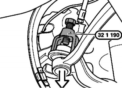
2. Loosen the nut and press out the tie rod using puller No.32 1 190.
When installing, there should be no traces of grease on the seat cone or in the hole; use a new self-locking nut.
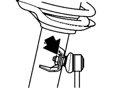
3. Disconnect the anti-roll bar from the suspension strut, holding the fastening unit from turning with a wrench. Remove the cable from the mounting bracket to the suspension strut.
When installing, use a new self-locking nut.
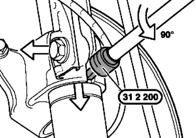
4. Remove the bolt, install tool No.31 2 200 into the slot and turn it through an angle of 90°. Leave the tool on the steering knuckle until installation.
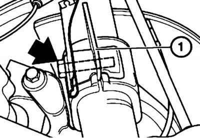
When installing, the bolt must enter the hole in the plate (1).
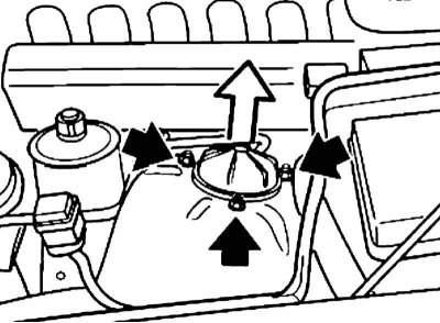
5. Remove the upper strut support cap. If so equipped, disconnect the EDC connector. Loosen the upper strut mounting nuts.
6. Press on the steering knuckle with the wishbone and the suspension arm brace so that the strut can be removed from the wheel arch. Disconnect the strut from the steering knuckle.
Avoid damaging the wheel arch; remove the strut with two people.
Disassembly and assembly
It is not permitted to use an impact wrench to compress and release device No.31 3 341, or to unscrew the bolts securing the upper support of the strut to the strut cylinder rod!
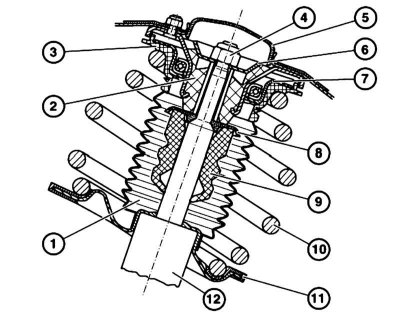
Suspension Strut Assembly Components
1 - Corrugated casing
2 — Upper support of the rack
3 - Upper spring insulating gasket
4 - Nut
5 - Cap
6 — Upper support travel limiter
7 — Shock absorber support cushion
8 — Thrust washer
9 — Bumper
10 — Spring
11 - Lower spring insulating gasket
12 — Suspension strut
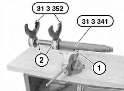
1. Clamp the sleeve (1) of device No.31 3 141 in a vice. The locking pins (2) must be locked with an audible click and with the feeling of the locking moment. Check the fastening of devices (horns) No.31 352 again.
The functionality of the devices should be checked before each use. Do not use damaged devices or change their design. Use only suitable horns installed from the chamfer of device No.31 3 141.
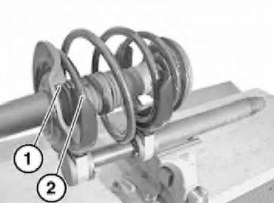
2. Install the spring between the horns so that its lower end (1) is under the horn and is coaxial with its end (2), and there are 3 turns of the spring between the horns.
When compressed, the spring coils should fully enter the recesses of the horns. Compress the spring only until the force is removed from the upper support of the suspension strut (not until the spring coils are adjacent to each other).
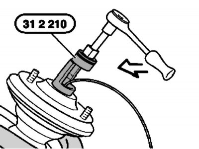
3. While holding the assembly from turning with an open-end wrench, loosen the nut using special tool No.31 2 210 or a 24 mm wrench.
The nut may only be loosened if both spring coils are completely in the recesses of the horns.
4. Remove the suspension strut.
5. When installing a new spring, release tool No.31 3 341, remove the old spring and compress the new one in accordance with the requirements described in paragraph 2.
6. Check the bellows, bump stop and spring insulating pads and replace any faulty parts if necessary.
7. Installation is carried out in the reverse order. The ends of the spring must coincide with the stepped stampings of the plates. Use a new self-locking nut for fastening the spring.
Do not release the device until the horns of the lower spring plate and the upper spring coil or the upper support of the strut touch. Otherwise, the device or spring may be damaged. Release the device only until the compression force is removed from the spring coils.
This article is available at russian, bulgarian, belarusian, ukrainian, serbian, croatian, romanian, polish, slovak, hungarian
Article verified: Polikarpov Saveliy
Share information:
Previous articles
БМВ E38: Front suspension
Next articles
Similar articles on other types of BMW cars:
Removal and installation the suspension strut spring BMW 3 Series E21 (1975-1983)
Front suspension strut — removal, repair and installation BMW 3 Series E46 (1998-2006, petrol)
Removal and installation the front suspension strut assembly BMW 5 Series E28 (1981-1988)
Removal and installation the upper shock absorber support and… BMW 5 Series E12 (1972-1981)
Removal and installation the engine assembly BMW X3 E83 (2003-2010)
Removal and installation the engine BMW X5 E53 (1999-2006)
Link in different formats to this page
Visitor comments
No comments yet
- General information
- Introduction to guide
- Manual
- Maintenance
- Power unit
- Engine M60/1, M60/2 (petrol)
- M62 engine (petrol)
- M57 engine (diesel)
- M67 engine (diesel)
- Cooling system
- Fuel system (petrol)
- Fuel system (diesel)
- Exhaust system
- Ignition and control systems
- Charge and launch systems
- Transmission
- Clutch
- Mechanical gearbox
- Automatic gearbox
- Cardan and drive shafts
- Chassis
- Brake system
- Front suspension
- Rear suspension
- Steering
- Body
- Exterior
- Interior
- Electrical equipment
- Equipment and devices
- Lighting
- Heating and air conditioning
- Electrical circuits
- General information
- Care and maintenance
- Power unit
- Minor engine repair
- Engine overhaul
- Lubrication system
- Cooling system
- Ignition system
- Supply system
- Injection system (petrol)
- Injection system (diesel)
- Exhaust system
- Transmission
- Clutch
- Manual gearbox
- Automatic gearbox
- Cardan gear
- Rear axle and shafts
- Chassis
- Front suspension
- Rear suspension
- Steering
- Wheels and tires
- Brake system
- Body
- Body elements
- Electrical equipment
- Equipment and devices
- Electrical circuits