
Table of contents: Overhaul of the six-cylinder engine…↓ Overhaul of the twelve-cylinder…↓
- Home
- BMW 7 Series
- E32
- Power unit
- Engine overhaul
- Engine overhaul — sequence of disassembly and assembly
Engine overhaul — sequence of disassembly and assembly (BMW 7 Series E32)
Note: This chapter provides a general procedure for disassembling and assembling engines. For detailed information on checking individual engine components, see the following chapters.
Overhaul of the six-cylinder engine of the M30 series
Secure the removed engine. Drain the engine oil. Remove the distributor cap with cables.
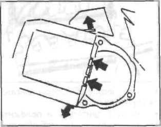
Remove the spark plugs. Remove the distributor rotor.
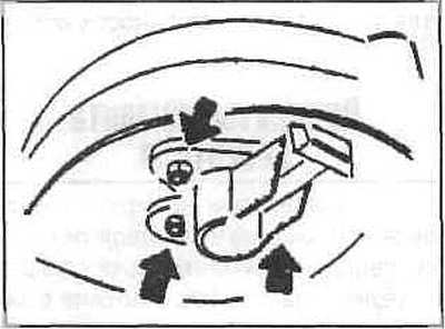
Turn the engine over until the piston of the first cylinder is at TDC and both valves are closed.
Fix the engine flywheel in this position.
Remove the chain tensioner from the front right.
Remove the chain sprocket from the camshaft and remove the chain.
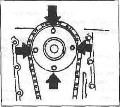
Loosen the cylinder head bolts (the engine must be cold).
Remove the cylinder head together with the intake and exhaust manifolds.
Immediately remove any water from the cylinder holes.
Tilt the engine and remove the oil pan.
Remove the V-belt pulley from the front of the engine.
Remove the lower front cover.
After loosening the damper flange mounting nut, remove the flange, chain and chain sprocket from the crankshaft.
Remove the oil pump, water pump and oil filter support.
Remove the clutch from the flywheel and the flywheel.
Remove the front cover under the flywheel.
Loosen the connecting rod bearing bolts and remove the bearing caps. Place the caps so that they can be installed in the same position.
Remove the pistons together with the connecting rods upwards.
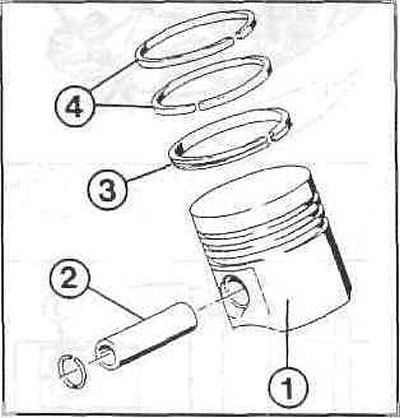
Elements of the piston group
1 — piston;
2 - piston pin;
3 - oil scraper ring;
4 - compression ring.
Replace the connecting rod bearing caps and tighten the bolts slightly.
Remove the bearing shells from the crankshaft and install them in the corresponding connecting rod bearings.
Loosen the main bearing cap bolts and remove the bearing caps.
Remove the crankshaft from the block.
Place all parts so that they do not get damaged.
Clean all parts.
After all parts and components have been checked for wear, you can begin assembling the engine.
Insert the main bearings into the block beds.
Place the crankshaft into the block, lubricate the journals, and install the main bearing caps.
Tighten the bolts to 58-63Nm.
After tightening, check the crankshaft for ease of movement. If it sticks, loosen the bearings one by one until the sticking bearing is found.
Insert the pistons with connecting rods into the cylinders.
Lubricate the connecting rod bearings and install the corresponding caps.
The arrow on the piston crown should point forward in the engine.
Tighten the connecting rod bolts to 52-57 Nm.
Use new bolts for each installation.
Check the crank travel. Install the rear cover with a new gasket.
Insert the chain drive wheel and put on the chain.
Install the oil pump. The pads under the pump are selected so that the chain has a play of 3-4 mm. The chain should not be pulled too tight.
Install the chain guide and insert the sliding tip.
Slide the damper flange onto the crankshaft and secure it in place.
The nut is finally tightened after the flywheel is installed.
Install the lower front cover with a new gasket.
Pull the chain to the top hole and secure it with wire so it cannot fall.
Secure the damper and the new belt pulley to the flange.
Install the oil pan.
Install the flywheel onto the drive shaft and tighten to 105 Nm. Use only new serrated bolts.
Fix the crankshaft through the flywheel and tighten the nut to 440 Nm.
Install the oil filter support and screw the new filter on by hand.
Clean the cylinder head sealing surfaces.
Position the new cylinder head gasket so that the TOP mark on the gasket is on top and the FRONT mark is near the chain. Remove the gasket from the packaging immediately before use, otherwise it will oxidize. Turn the crankshaft so that the piston of the first cylinder is in the TDC position.
Before installing the cylinder head, make sure that the valves of the first cylinder are closed.
Place the cylinder head on the block and hand-tighten the bolts into the dry holes. Lightly lubricate the bolts for installation.
Tighten the bolts as follows:
- Step 1: Tighten the bolts to 60 Nm.
- 2nd move - pull to 33°.
- 3rd step - after 25 minutes of warming up, turn it to an angle of 35°.
Install the chain with the sprocket so that the locating pin is on the bottom left when the threaded holes on the flange are vertical and horizontal.
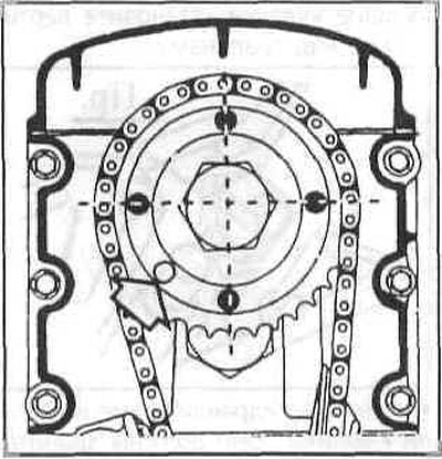
Tighten the chain sprocket to 10 Nm.
Install the chain tensioner onto the front cover and fill with oil.
Rotate the crankshaft two revolutions. Watch for ease of rotation. If resistance is felt, check the camshaft installation.
Turn the crankshaft to the TDC position of the piston of the first cylinder and check the installation of the camshaft.
Otherwise, install correctly.
Install the front cylinder head cover.
Install the distributor rotor flange onto the camshaft and tighten the bolt with a new sealing ring.
Install the distributor rotor.
Adjust the valve clearances. Install the spark plugs and put on the distributor cap.
Install the valve cover.
Install all auxiliary units. Tighten the V-belt so that it can be pressed by a finger by 8-10 mm on the longest branch.
Overhaul of the twelve-cylinder engine of the M70 series
Secure the engine.
Remove the air intake manifold.
Disconnect the vacuum hoses of the pressure regulator. Loosen the bolts securing the injection tubes and remove them together with the injection fans.
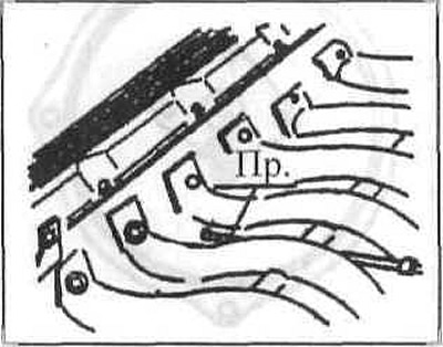
Disconnect the engine crankcase ventilation hose.
Remove the throttle body fittings from the manifolds.
Loosen the intake manifold fitting nuts.
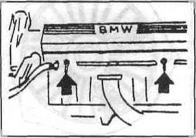
Remove the protective strip of the liners.
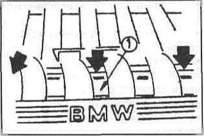
Unscrew the manifold using a T-wrench with a swivel head.
Unscrew the distributor runners.
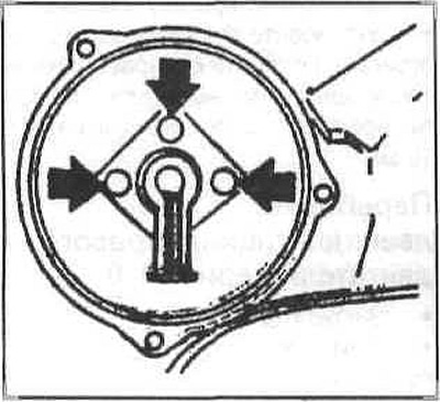
Unscrew the runner attachments from the camshafts.
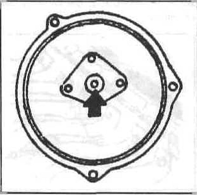
Remove the polymer insert and unscrew the three bolts. Remove the cover.
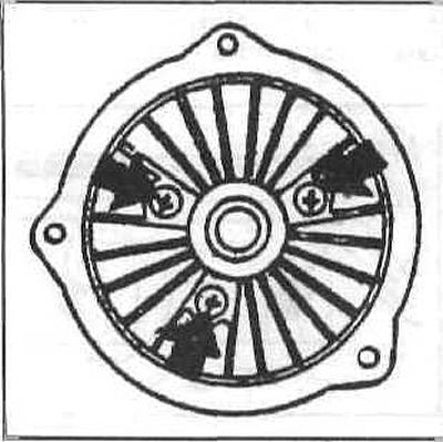
Unscrew the rubber bearings from the valve covers.
Elements of the gas distribution mechanism of the M70 series engine
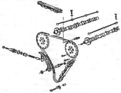
Remove the valve covers.
Remove the top timing gear cover.
Remove the valve levers with a tool. To do this, install the corresponding cams vertically above the valves.
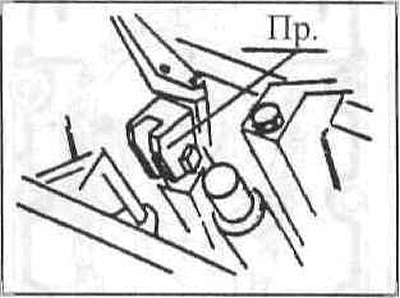
Remove the hydraulic valve lifters. They should be stored vertically to prevent oil from leaking out.
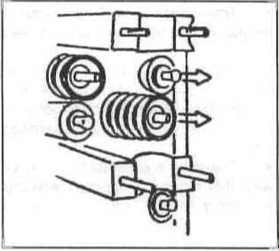
Remove the camshafts. Set the piston of the first cylinder to the ignition position.
Loosen the lock nut, loosen the mounting bolt. Unscrew the lock bolt, remove the tension piston. Remove the central bar of the amplifier.
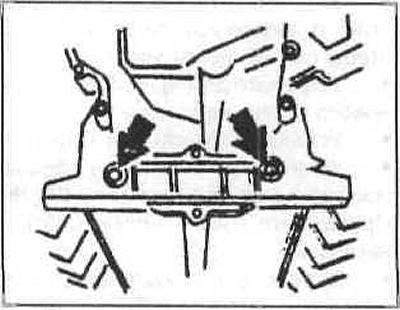
Unscrew the sprocket of the cylinder chain 1-6.
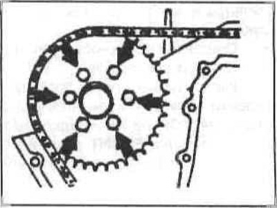
Loosen the bolt of the left damper bar and pull the bar up.
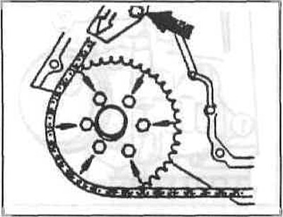
Loosen the chain sprocket bolts and remove the sprocket.
Remove the cylinder head oil lines.
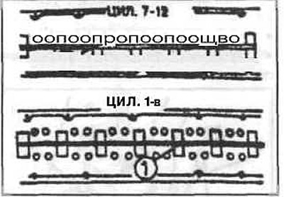
After removing the camshaft bearing caps, remove the crankshaft camshafts Remove the rear portion of the upper timing gear case.
The box is located in the center of the cylinder heads on guide bushings.
Remove the coolant manifold between the cylinder heads at the rear.
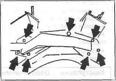
Remove the alternator.
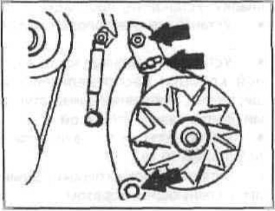
Remove the damper by locking the flywheel with a device.
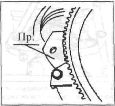
Loosen the damper bolts and remove it.
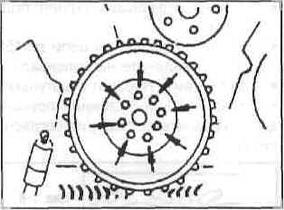
Unscrew the damper hub from the crankshaft.
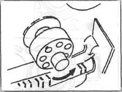
Remove the hub with a tool. Remove the cylinder heads.
Remove the water pump.
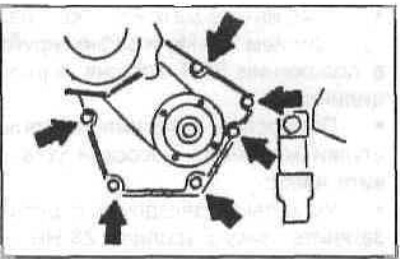
Use bolts to push the pump away from the mounting block.
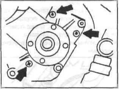
Remove the oil pan.
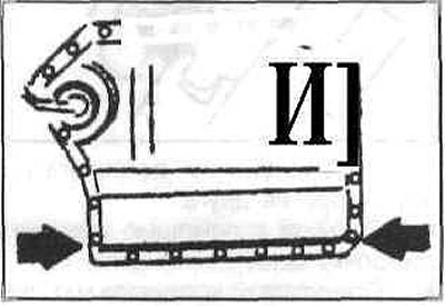
Loosen the oil pump chain sprocket mounting nuts. Remove the sprocket.
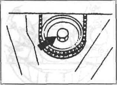
Remove the oil pump.
Remove the lower timing gear cover. To do this, remove the reference signal sensor.

Unscrew the mounting bolts and remove the cover.
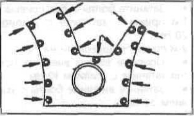
Loosen the connecting rod bearing caps and remove the pistons together with the connecting rods.
Mark the installation position of the connecting rods, if the pistons are separated from the connecting rods, also mark the installation position.
The connecting rods and caps are marked with numbers.
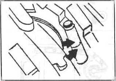
The numbers must be located opposite each other.
Remove the chain sprocket from the crankshaft using a puller.
Unscrew the flywheel and driven clutch disc from the crankshaft.
Remove the rear bearing cover.
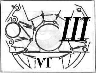
Remove the main bearing cap and take out the crankshaft.
After all parts have been checked, assemble the engine.
Place the crankshaft into the lubricated block liners.
Install the main bearing cap with the bushings fully seated.
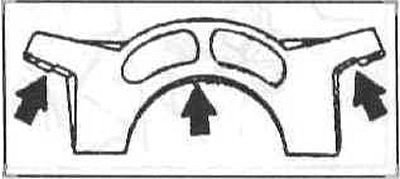
Screw in the inner bearing bolts by hand.
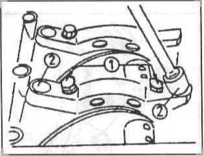
Tighten the bolts in two steps:
- Step 1: Tighten to 20 Nm.
- 2nd move - turn it 70°.
Tighten the outer bolt support bushings to 10 Nm.
Tighten the outer bolts to 34 Nm.
Tighten the oil pump supports to 34 Nm.
After tightening, check the crankshaft for ease of movement. If it is sticking, loosen the bearings one by one until the sticking one is found.
Install the rear bearing cover.
Heat the chain sprocket to 150-200°C and place it on the crankshaft.
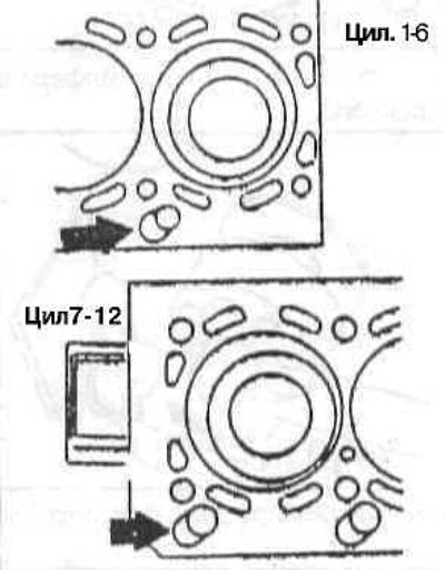
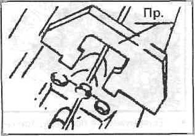
Install the pistons with connecting rods. When installed, the pistons should take the position as shown in the figure.
Install the connecting rod caps and tighten in two steps:
- 1st step - with a force of 20 Nm,
- 2nd step - turn up to 70.
Insert the chain and install the timing gear box (tensioner bar installed).
Install the oil pump chain.
Install the upper part of the oil pan.
Screw the flywheel to the crankshaft with a force of 100 Nm and fix it in the TDC position of the piston of the first cylinder.
Fully tighten the oil pump support bushings and install the pump.
Install the sprocket with the chain. Tighten the nut to 28 Nm.
Rotate the support bushings so that the chain can sag by 7+1 mm.
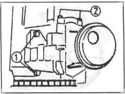
Tighten the support bolt to 24 Nm.
Press in the damper hub. Tighten the bolt to 440 Nm.
Screw the damper with a torque of 24 Nm.
Install the generator.
Measure the piston protrusion with a gauge.
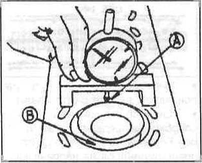
Install the device with the frame on the block and set the scale to "0".
Move the device to point A and set the highest point by turning the crankshaft.
Move the device to point B and determine the value.
Size A+B will give protrusion.
Perform this measurement on 6 pistons.
The average size will determine the thickness of the gasket.
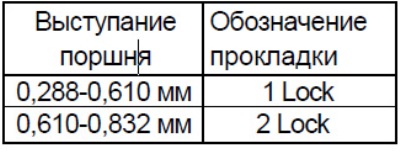
Select the appropriate gasket. Install the gaskets.
Install both cylinder heads.
Install the rear of the upper timing gear case with the guide bushings. Tighten the bolts by hand.
After tightening the head, tighten to 10 Nm.
Tighten the cylinder head bolts as follows:
- 1st dose – 30 Nm – 15 minute break.
- 2nd step - rotate at an angle of 120°.
Cylinder head bolt tightening sequence
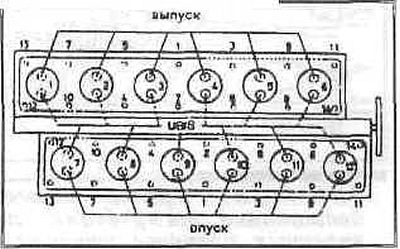
Turn the engine to the TDC point of the first cylinder and fix the flywheel.
Install both camshafts as shown in the figure and tighten the bearing caps to 15 Nm.
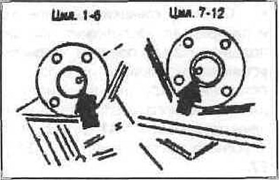
Set the camshaft to the required position using the tool.
Install the chain with sprockets against the direction of travel so that it can be tensioned in the groove area.
Lightly tighten the sprocket nuts.
Install the guide bars and tighten the chain sprockets to the installation position.
Chain mounting elements
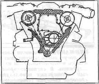
Install the chain tensioner.
Loosen the set bolt completely.
Turn the engine one revolution in the direction of travel. Measure size A.
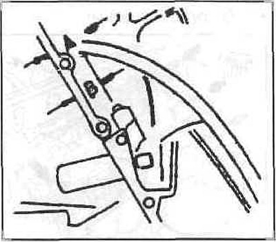
Press the tensioner bar all the way against the spring force.
Measure dimension B. The difference should be A-B = 6±0.5 mm. Screw in the set bolt and tighten the lock nut.
Turn the crankshaft to the TDC of the piston of the first cylinder and use a feeler gauge to check the position of the camshaft.
Insert hydraulic lifters.
Insert the guide plates into the valve plates. Insert the levers. Install the oil lines.
Install the cylinder head covers.
Use a feeler gauge to center the distributor cap and tighten the fastener.
Install the adapter with the guide pin.
Further assembly is carried out in the reverse order of removal.
The article text was copied from an online resource «bmwman»
This article is available at russian, bulgarian, belarusian, ukrainian, serbian, croatian, romanian, polish, slovak, hungarian
Article verified: Sevastyanov Nikolay
Share information:
Previous articles
БМВ E32: Engine overhaul
Next articles
Similar articles on other types of BMW cars:
Disassembly and assembly of the engine BMW 3 Series E21 (1975-1983)
Engine Repair — Disassembly Sequence BMW 3 Series E46 (1998-2006, petrol)
Sequence of engine assembly during major repairs BMW 5 Series E28 (1981-1988)
Disassembly and assembly of the front wheel brake mechanism BMW 5 Series E12 (1972-1981)
Removal and installation the engine assembly BMW X3 E83 (2003-2010)
Features of winter operation of a diesel engine BMW X5 E53 (1999-2006)
Disassembly and assembly of the engine BMW 3 Series E21 (1975-1983)
Engine Repair — Disassembly Sequence BMW 3 Series E46 (1998-2006, petrol)
Sequence of engine assembly during major repairs BMW 5 Series E28 (1981-1988)
Disassembly and assembly of the front wheel brake mechanism BMW 5 Series E12 (1972-1981)
Removal and installation the engine assembly BMW X3 E83 (2003-2010)
Features of winter operation of a diesel engine BMW X5 E53 (1999-2006)
Link in different formats to this page
Visitor comments
No comments yet
- General information
- Introduction to guide
- Manual
- Maintenance
- Power unit
- Engine M60/1, M60/2 (petrol)
- M62 engine (petrol)
- M57 engine (diesel)
- M67 engine (diesel)
- Cooling system
- Fuel system (petrol)
- Fuel system (diesel)
- Exhaust system
- Ignition and control systems
- Charge and launch systems
- Transmission
- Clutch
- Mechanical gearbox
- Automatic gearbox
- Cardan and drive shafts
- Chassis
- Brake system
- Front suspension
- Rear suspension
- Steering
- Body
- Exterior
- Interior
- Electrical equipment
- Equipment and devices
- Lighting
- Heating and air conditioning
- Electrical circuits
- General information
- Care and maintenance
- Power unit
- Minor engine repair
- Engine overhaul
- Lubrication system
- Cooling system
- Ignition system
- Supply system
- Injection system (petrol)
- Injection system (diesel)
- Exhaust system
- Transmission
- Clutch
- Manual gearbox
- Automatic gearbox
- Cardan gear
- Rear axle and shafts
- Chassis
- Front suspension
- Rear suspension
- Steering
- Wheels and tires
- Brake system
- Body
- Body elements
- Electrical equipment
- Equipment and devices
- Electrical circuits