
- Home
- BMW 7 Series
- E32
- Power unit
- Engine overhaul
- Cylinder head
Cylinder head (BMW 7 Series E32)
Carefully inspect the cylinder head for cracks, signs of coolant leakage, or other damage. If there are cracks and they cannot be repaired in a specialized workshop, the head must be replaced.
Using the edge of a ruler and a feeler gauge, check whether the surface of the cylinder head that contacts the cylinder block is deformed.
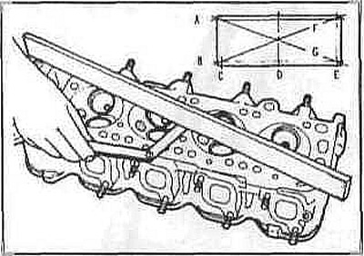
If the deformation is greater than the maximum permissible value (0.05 mm), the surface must be machined without exceeding the required maximum permissible value.
Check the valve seats in each combustion chamber. If they are burned, cracked or have pitting, the valve seats must be replaced.
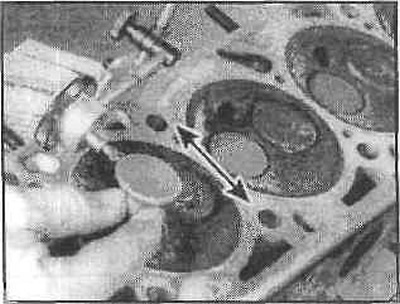
Check the clearance between the valve stem and the valve guide by measuring the horizontal clearance of the stem using a gauge with an indicator. To determine the clearance between the stem and the valve guide, swing the stem and take measurements at the extreme points using an indicator. The valve should be raised by approximately 1.5 mm. To obtain the true clearance value, divide the result by two. If the clearance is greater than the permissible value, the guide bushings must be replaced.
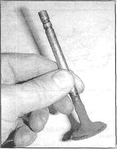
Carefully inspect each valve for signs of wear, cracks, dents, or burnt areas. Rotate the valve to see if it is bent. If any of these are found, the valve must be repaired at a specialist workshop.
Check the valve for wear.
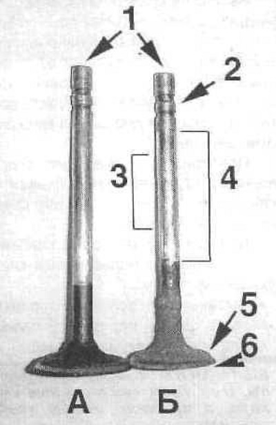
Checking valve wear at the indicated points
A - inlet valve;
B - exhaust valve;
1 - end of valve;
2 - cracker groove;
3 — rod (least worn section);
4 — rod (the most worn out section);
5 — valve surface;
6 — edge.
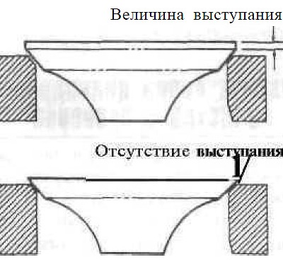
Measure the amount of protrusion of each valve relative to the seat (for the intake valve - 1.191 mm, for the exhaust valve - 1.98 mm). If it is less or absent, the valve must be replaced.
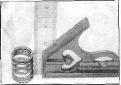
Check each valve spring for wear (at the ends) and pitting. Measure the free length and compare with the technical data. Springs shorter than the permissible length cannot be used again. The tension of all springs must be checked with a special device before deciding on their suitability (these measurements are carried out in a specialized workshop).
Place each spring on a flat surface and check for squareness.
If the springs are deformed, replace them as they may cause accelerated wear of the guide bushings.
Check the plates and holders for wear and cracks. Any questionable parts should be replaced with new ones.
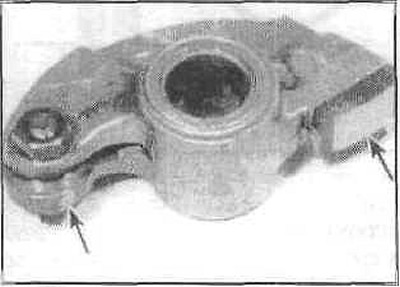
Check the rocker arm areas that contact the pushrod ends and valve stems for pitting, wear, plaque, and scratches. Also check the joints. Check for cracks in the rocker arms, bolts, and nuts.
All damaged or badly worn parts should be replaced with new ones.
If the inspection shows that the valve parts are in poor condition and worn beyond the permissible limits (what usually happens in engines undergoing repair) it is necessary to replace or grind the valves and seats.
Using the edge of a ruler and a feeler gauge, check whether the surface of the cylinder head that contacts the cylinder block is deformed.
If the deformation is greater than the maximum permissible value (0.05 mm), the surface must be machined without exceeding the required maximum permissible value.
Check the valve seats in each combustion chamber. If they are burned, cracked or have pitting, the valve seats must be replaced.
Check the clearance between the valve stem and the valve guide by measuring the horizontal clearance of the stem using a gauge with an indicator. To determine the clearance between the stem and the valve guide, swing the stem and take measurements at the extreme points using an indicator. The valve should be raised by approximately 1.5 mm. To obtain the true clearance value, divide the result by two. If the clearance is greater than the permissible value, the guide bushings must be replaced.
Valves
Carefully inspect each valve for signs of wear, cracks, dents, or burnt areas. Rotate the valve to see if it is bent. If any of these are found, the valve must be repaired at a specialist workshop.
Check the valve for wear.
Checking valve wear at the indicated points
A - inlet valve;
B - exhaust valve;
1 - end of valve;
2 - cracker groove;
3 — rod (least worn section);
4 — rod (the most worn out section);
5 — valve surface;
6 — edge.
Measure the amount of protrusion of each valve relative to the seat (for the intake valve - 1.191 mm, for the exhaust valve - 1.98 mm). If it is less or absent, the valve must be replaced.
Valve parts
Check each valve spring for wear (at the ends) and pitting. Measure the free length and compare with the technical data. Springs shorter than the permissible length cannot be used again. The tension of all springs must be checked with a special device before deciding on their suitability (these measurements are carried out in a specialized workshop).
Place each spring on a flat surface and check for squareness.
If the springs are deformed, replace them as they may cause accelerated wear of the guide bushings.
Check the plates and holders for wear and cracks. Any questionable parts should be replaced with new ones.
Rocker arm parts
Check the rocker arm areas that contact the pushrod ends and valve stems for pitting, wear, plaque, and scratches. Also check the joints. Check for cracks in the rocker arms, bolts, and nuts.
All damaged or badly worn parts should be replaced with new ones.
If the inspection shows that the valve parts are in poor condition and worn beyond the permissible limits (what usually happens in engines undergoing repair) it is necessary to replace or grind the valves and seats.
This article is available at russian, bulgarian, belarusian, ukrainian, serbian, croatian, romanian, polish, slovak, hungarian
Article verified: Sevastyanov Nikolay
Share information:
Previous articles
БМВ E32: Engine overhaul
Next articles
Similar articles on other types of BMW cars:
Cylinder head characteristics BMW 3 Series E21 (1975-1983)
Removal and installation the cylinder head BMW 3 Series E30 (1982-1994)
Cylinder Head Specifications BMW 5 Series E12 (1972-1981)
Removal and installation of cylinder head — engines M20, M21, M30 BMW 5 Series E34 (1988-1996)
Cylinder head BMW X3 E83 (2003-2010)
Cylinder head — design description BMW X5 E53 (1999-2006)
Link in different formats to this page
Visitor comments
No comments yet
- General information
- Introduction to guide
- Manual
- Maintenance
- Power unit
- Engine M60/1, M60/2 (petrol)
- M62 engine (petrol)
- M57 engine (diesel)
- M67 engine (diesel)
- Cooling system
- Fuel system (petrol)
- Fuel system (diesel)
- Exhaust system
- Ignition and control systems
- Charge and launch systems
- Transmission
- Clutch
- Mechanical gearbox
- Automatic gearbox
- Cardan and drive shafts
- Chassis
- Brake system
- Front suspension
- Rear suspension
- Steering
- Body
- Exterior
- Interior
- Electrical equipment
- Equipment and devices
- Lighting
- Heating and air conditioning
- Electrical circuits
- General information
- Care and maintenance
- Power unit
- Minor engine repair
- Engine overhaul
- Lubrication system
- Cooling system
- Ignition system
- Supply system
- Injection system (petrol)
- Injection system (diesel)
- Exhaust system
- Transmission
- Clutch
- Manual gearbox
- Automatic gearbox
- Cardan gear
- Rear axle and shafts
- Chassis
- Front suspension
- Rear suspension
- Steering
- Wheels and tires
- Brake system
- Body
- Body elements
- Electrical equipment
- Equipment and devices
- Electrical circuits