
- Home
- BMW 3 Series
- E30
- Power unit
- M10/M20 engine
- Removal and installation the cylinder head
Removal and installation the cylinder head (BMW 3 Series E30)
Signs of a faulty cylinder head gasket include:
Remove the front exhaust pipe.
Drain the coolant.
Remove the air filter (see section "Removal and installation the air filter").
Disconnect the ground cable from the battery.
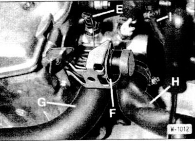
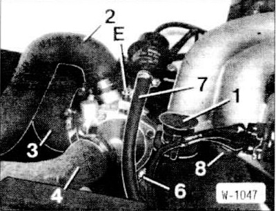
Disconnect the water hoses "G" and "H", having first completely released and pulled back the clamps. Cut the clamps with side cutters and replace them with screw clamps during installation.
Unscrew the diagnostic connector "F" and put it aside.
Disconnect the temperature switch connector "E".
Carburetor engines: Disconnect fuel hose "I" from the mechanical fuel pump.
Disconnect connectors "J" and "K".
Disconnect the vacuum hose "L" from the intake manifold, which goes to the brake booster.
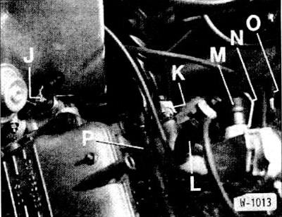
Disconnect the "M" connector from the actuator motor, having first moved the "N" bracket away.
Release the clamps securing the wiring harness "P" and pull out the wiring harness.
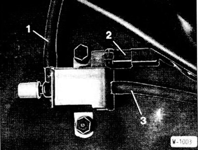
Disconnect the vacuum hoses "1", "2", "3" from an electric changeover valve.
Disconnect all water hoses from the cylinder head.
All fuel and vacuum hoses attached to the cylinder head and intake manifold must be marked with adhesive tape and disconnected.
All electrical wires leading to the cylinder head and carburetor should be marked with adhesive tape and disconnected.
Remove all spark plug caps, then the spark plug wires together with the distributor cap (see section "Removal and installation the ignition distributor").
Disconnect the electrical wires from the ignition distributor.
Remove the throttle cable (see section "Adjusting the throttle cable").
Unscrew the intake manifold support.
Disconnect the electrical wires from the starter.
Unscrew the oil dipstick tube support.
Clean the injection tubes on the fuel dispenser and then unscrew them. To prevent dirt from getting in, close the ends of the tubes and the fittings on the dispenser with plugs.
Disconnect the engine warm-up mode controller connector.
Shine connectors from injectors. On a six-cylinder engine, remove connectors from injectors "1", "2", "3" and from the oil valve and pull the wiring harness under the intake manifold. Remove the additional air damper connectors from the injectors "4", "5", "6".
Press the ventilation tube down and secure it in this position using the BMW 111290 tool.
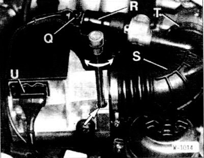
Disconnect the U-connector of the air flow meter and the "Q" connector of the idle speed control valve "R". Unscrew the control valve.
Disconnect the "S" hose from the intake manifold.
Release the T-clamp.
Unscrew the air flow meter and remove it together with the air filter and control valve.
Unscrew the diagnostic connector 1.
Disconnect the water hoses "2", "3", "4", "6". First, completely release and move the clamps back.
Disconnect fuel hose "7".
Unscrew the holder "8".
Remove the V-belt (see section "Removal and installation the alternator V-belt. Replacing the V-belt").
Lift the top dead center sensor wire and pull it out together with the protective cover.
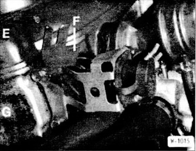
Remove the cylinder head cover "E" (see section "Removal and installation the cylinder head cover").
Unscrew the cover "G" of the camshaft toothed pulley and remove it together with the bracket "F".
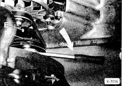
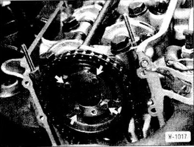
Set the engine to the top dead center of ignition of the 1st cylinder. To do this, set the gearbox to neutral, tighten the handbrake. Turn the crankshaft with a 27 mm wrench head with an extension with a ratchet mechanism for the central bolt of the crankshaft pulley in the direction of engine rotation, i.e. clockwise, until the following marks coincide.
The "F" mark on the belt pulley must match the "E" mark on the timing gear cover.
The mark on the distributor rotor must match the mark on the distributor body.
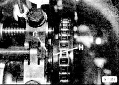
At the same time, the "H" mark on the camshaft boss must coincide with the "G" protrusion on the cylinder head.
Six-cylinder engine: The timing belt is not completely removed from the camshaft timing pulley.
Remove the ignition distributor (see section "Removal and installation the ignition distributor").
Remove the chain tensioner piston (see section "Removal and installation, checking of the chain tensioner").
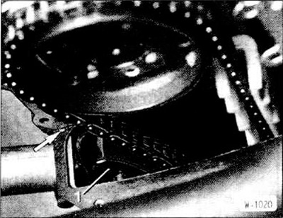
Mark the relative positions of the camshaft sprockets and the chain. To do this, draw a line along the chain and sprocket with a scriber or paint them so that when reassembling, the chain is installed on the sprocket in the same position.
Loosen the fastening bolts (arrows). To do this, lightly tap the handle of the wrench to overcome the tightening torque.
Remove the camshaft sprocket.
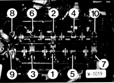
Loosen the cylinder head mounting bolts in the reverse order, i.e. 10-1. On a six-cylinder engine, loosen the cylinder head bolts 14-1, in the same order as on a four-cylinder engine.
Remove the cylinder head.
Before installation, clean the cylinder head and cylinder block from the remains of the old seal. Do not allow the remains of the seal to get into the cylinder holes.
Cover the cylinder holes with rags.
Measure the flatness of the cylinder head and engine block with a steel ruler in the longitudinal and transverse directions and, if necessary, mill it (work at a service station). If the cylinder head is milled, the camshaft sprocket cover must also be milled to the same size.
Check the cylinder head for cracks and the cylinder running surfaces for scratches.
Thoroughly clean the cylinder head bolt holes from oil and other residues.
Be sure to replace the cylinder head gasket.
Apply a new gasket without sealing compound so that it does not cover the holes.
Before installing the cylinder head, check that the camshaft is at top dead center.
Install the cylinder head.
Be sure to replace and lightly lubricate the cylinder head bolts with engine oil. On six-cylinder engines produced from September 1987 onwards, only use bolts with hexagon socket heads.
Insert and tighten the cylinder head bolts by hand. Caution: Tighten the cylinder head bolts very carefully. Before tightening the bolts, check the accuracy of the torque wrench. In addition, a protractor, such as the HAZET 6690, is required to tighten the cylinder head bolts.

On the 1st pass, tighten the cylinder head bolts with a torque wrench to a tightening torque of 60 Nm. After this, wait about 15 minutes for the bolts to settle.
On the 2nd pass, tighten the head bolts with a rigid wrench at an angle of 33±3°.
On the 1st pass, tighten the cylinder head bolts with a torque wrench to a tightening torque of 40-45 Nm. After this, wait about 15 minutes for the bolts to settle.
On the 2nd pass, tighten the cylinder head bolts with a torque wrench to a tightening torque of 50-65 Nm.
Six-cylinder engine produced since September 1987 with Allen-head cylinder head bolts:
Check the engagement of the chain with the teeth of the crankshaft sprocket. Check that the camshaft and crankshaft sprockets are in the top dead center position.
Insert the sprocket into the chain so that the marks made during removal match. The hole for the locking pin should be located at the bottom.
Place the sprocket on the camshaft and tighten it with a tightening torque of 7 Nm.
Install the chain tensioner piston (see section "Removal and installation, checking of the chain tensioner").
Place the toothed belt on the camshaft toothed pulley and tighten it (see section "Removal and installation the timing belt").
Check again that the camshaft and crankshaft are in the top dead center position.
Install the ignition distributor, connect the ignition wires (see section "Removal and installation the ignition distributor").
Screw on the camshaft sprocket cover together with the air filter housing bracket. Pre-fill the holes (arrows) on the left and right in the cylinder head gasket with a liquid universal sealing compound, such as Curil. Then glue the new cover gasket with a small amount of grease. Install the cover and first slightly tighten the lower bolts. Screw in and tighten the remaining bolts to the required torque, then tighten both lower bolts. Tightening torque: M6 bolts - 10 Nm, M8 bolts - 22 Nm.
Adjust the valve clearances (see section "Checking and adjusting valve clearances").
Install the cylinder head cover (see section "Removal and installation the cylinder head cover").
Tighten the oil dipstick guide tube mount.
Screw the fuel injection pipes to the fuel dispenser.
Connect the connector to the engine warm-up controller.
Screw the bracket to the intake manifold.
Connect the fuel hose to the pressure regulator and secure it with clamps.
Screw on the diagnostic connector.
Connect and secure all water hoses to the coolant regulator housing with clamps.
Install the spark plugs (see section "Spark plugs").
Insert the TDC sensor wire with the protective cap.
Install and tension the V-belt (see section "Removal and installation the alternator V-belt. Replacing the V-belt").
Check the ventilation hose sealing ring for cracks or damage and replace it if necessary. Remove BMW tool 111209 and ensure that the ventilation hose returns to its original position.
Insert and screw the air filter housing together with the air flow meter and idle control valve. Connect the electrical wires.
Tighten the intake manifold support.
Install and tension the V-belt (see section "Removal and installation the alternator V-belt. Replacing the V-belt"),
Connect and secure all water, fuel and vacuum hoses with clamps.
Connect all electrical wires in accordance with the markings made.
Install and adjust the throttle cable.
Secure the wiring harness to the cylinder head with clamps.
Screw on the diagnostic connector.
Bolt the front exhaust pipe to the exhaust manifold.
Connect the ground wire to the battery.
Install the air filter (see section "Removal and installation the air filter").
Fill the cooling system with coolant (see section "Replacing the coolant").
Check the engine oil level. If the cylinder head was removed due to a faulty gasket, it is recommended to change the engine oil and replace the oil filter, as coolant may have entered the oil.
Check and, if necessary, adjust the ignition timing.
Start the engine and warm it up for 25 minutes.
Remove the cylinder head cover (see section "Removal and installation the cylinder head cover").
Engines with Allen-head cylinder head bolts: Tighten all cylinder head bolts in sequence 1-10 (on a six-cylinder engine - 1-14) with a rigid wrench by 25-30°.
Install the cylinder head cover (see section "Removing and installing the cylinder head cover").
Check and, if necessary, adjust the idle speed and CO content (see section "Ignition timing, CO content, idle speed").
Cylinder head bolt tightening torque for 324d/td:
- Reduced engine power.
- Decrease in coolant level, white smoke from exhaust gases when the engine is warm.
- Coolant in engine oil. Oil level does not decrease, but rather increases. Gray color of engine oil, foam on the oil dipstick. Oil dilution.
- Engine oil in coolant, loss of oil.
- Lack of compression in two adjacent cylinders.
Removal
Remove the front exhaust pipe.
Drain the coolant.
Remove the air filter (see section "Removal and installation the air filter").
Disconnect the ground cable from the battery.
Disconnect the water hoses "G" and "H", having first completely released and pulled back the clamps. Cut the clamps with side cutters and replace them with screw clamps during installation.
Unscrew the diagnostic connector "F" and put it aside.
Disconnect the temperature switch connector "E".
Carburetor engines: Disconnect fuel hose "I" from the mechanical fuel pump.
Disconnect connectors "J" and "K".
Disconnect the vacuum hose "L" from the intake manifold, which goes to the brake booster.
Disconnect the "M" connector from the actuator motor, having first moved the "N" bracket away.
Release the clamps securing the wiring harness "P" and pull out the wiring harness.
Disconnect the vacuum hoses "1", "2", "3" from an electric changeover valve.
Disconnect all water hoses from the cylinder head.
All fuel and vacuum hoses attached to the cylinder head and intake manifold must be marked with adhesive tape and disconnected.
All electrical wires leading to the cylinder head and carburetor should be marked with adhesive tape and disconnected.
Remove all spark plug caps, then the spark plug wires together with the distributor cap (see section "Removal and installation the ignition distributor").
Disconnect the electrical wires from the ignition distributor.
Remove the throttle cable (see section "Adjusting the throttle cable").
Unscrew the intake manifold support.
Disconnect the electrical wires from the starter.
Model 318i with K-Jetronic
Unscrew the oil dipstick tube support.
Clean the injection tubes on the fuel dispenser and then unscrew them. To prevent dirt from getting in, close the ends of the tubes and the fittings on the dispenser with plugs.
Disconnect the engine warm-up mode controller connector.
Vehicles with L/LE- Jetronic or Motronic
Shine connectors from injectors. On a six-cylinder engine, remove connectors from injectors "1", "2", "3" and from the oil valve and pull the wiring harness under the intake manifold. Remove the additional air damper connectors from the injectors "4", "5", "6".
Press the ventilation tube down and secure it in this position using the BMW 111290 tool.
Disconnect the U-connector of the air flow meter and the "Q" connector of the idle speed control valve "R". Unscrew the control valve.
Disconnect the "S" hose from the intake manifold.
Release the T-clamp.
Unscrew the air flow meter and remove it together with the air filter and control valve.
Unscrew the diagnostic connector 1.
Disconnect the water hoses "2", "3", "4", "6". First, completely release and move the clamps back.
Disconnect fuel hose "7".
Unscrew the holder "8".
Remove the V-belt (see section "Removal and installation the alternator V-belt. Replacing the V-belt").
Lift the top dead center sensor wire and pull it out together with the protective cover.
Remove the cylinder head cover "E" (see section "Removal and installation the cylinder head cover").
Unscrew the cover "G" of the camshaft toothed pulley and remove it together with the bracket "F".
Note: The lid is partially glued. Release the lid by gently hitting it with your palms or using a plastic hammer.
Set the engine to the top dead center of ignition of the 1st cylinder. To do this, set the gearbox to neutral, tighten the handbrake. Turn the crankshaft with a 27 mm wrench head with an extension with a ratchet mechanism for the central bolt of the crankshaft pulley in the direction of engine rotation, i.e. clockwise, until the following marks coincide.
The "F" mark on the belt pulley must match the "E" mark on the timing gear cover.
The mark on the distributor rotor must match the mark on the distributor body.
At the same time, the "H" mark on the camshaft boss must coincide with the "G" protrusion on the cylinder head.
Six-cylinder engine: The timing belt is not completely removed from the camshaft timing pulley.
Remove the ignition distributor (see section "Removal and installation the ignition distributor").
Remove the chain tensioner piston (see section "Removal and installation, checking of the chain tensioner").
Mark the relative positions of the camshaft sprockets and the chain. To do this, draw a line along the chain and sprocket with a scriber or paint them so that when reassembling, the chain is installed on the sprocket in the same position.
Loosen the fastening bolts (arrows). To do this, lightly tap the handle of the wrench to overcome the tightening torque.
Remove the camshaft sprocket.
Caution: Do not turn the crankshaft with the chain or timing belt removed.
Loosen the cylinder head mounting bolts in the reverse order, i.e. 10-1. On a six-cylinder engine, loosen the cylinder head bolts 14-1, in the same order as on a four-cylinder engine.
Remove the cylinder head.
Caution: After removal, do not place the cylinder head on the contact surface, as this may damage the open valves. Therefore, place the cylinder head on two wooden spacers.
Installation
Before installation, clean the cylinder head and cylinder block from the remains of the old seal. Do not allow the remains of the seal to get into the cylinder holes.
Cover the cylinder holes with rags.
Measure the flatness of the cylinder head and engine block with a steel ruler in the longitudinal and transverse directions and, if necessary, mill it (work at a service station). If the cylinder head is milled, the camshaft sprocket cover must also be milled to the same size.
Check the cylinder head for cracks and the cylinder running surfaces for scratches.
Thoroughly clean the cylinder head bolt holes from oil and other residues.
Caution: There must be no oil in the recesses, otherwise the bolts will not fully tighten the cylinder head, despite being tightened to the required torque. In addition, the engine block may be torn apart.
Be sure to replace the cylinder head gasket.
Apply a new gasket without sealing compound so that it does not cover the holes.
Note: With a milled cylinder head, a cylinder head gasket of normal thickness or 0.3 mm thicker can be installed, depending on the height of the modified cylinder head. Installing a thicker gasket prevents a reduction in the volume of the combustion chambers.
Before installing the cylinder head, check that the camshaft is at top dead center.
Install the cylinder head.
Be sure to replace and lightly lubricate the cylinder head bolts with engine oil. On six-cylinder engines produced from September 1987 onwards, only use bolts with hexagon socket heads.
Insert and tighten the cylinder head bolts by hand. Caution: Tighten the cylinder head bolts very carefully. Before tightening the bolts, check the accuracy of the torque wrench. In addition, a protractor, such as the HAZET 6690, is required to tighten the cylinder head bolts.
Note: On each pass, tighten the cylinder head bolts in sequence 1-10, on a six-cylinder engine - 1-14.
Four-cylinder engine M10
On the 1st pass, tighten the cylinder head bolts with a torque wrench to a tightening torque of 60 Nm. After this, wait about 15 minutes for the bolts to settle.
On the 2nd pass, tighten the head bolts with a rigid wrench at an angle of 33±3°.
Six-cylinder engine
On the 1st pass, tighten the cylinder head bolts with a torque wrench to a tightening torque of 40-45 Nm. After this, wait about 15 minutes for the bolts to settle.
On the 2nd pass, tighten the cylinder head bolts with a torque wrench to a tightening torque of 50-65 Nm.
Six-cylinder engine produced since September 1987 with Allen-head cylinder head bolts:
- 1st pass - tightening with a torque wrench to a torque of 30 Nm.
- 2nd pass - tighten with a rigid wrench at an angle of 90°.
- 3rd pass - tighten with a rigid wrench at an angle of 90°. Note: Take breaks between individual passes; there is no need to warm up the engine.
Check the engagement of the chain with the teeth of the crankshaft sprocket. Check that the camshaft and crankshaft sprockets are in the top dead center position.
Insert the sprocket into the chain so that the marks made during removal match. The hole for the locking pin should be located at the bottom.
Place the sprocket on the camshaft and tighten it with a tightening torque of 7 Nm.
Install the chain tensioner piston (see section "Removal and installation, checking of the chain tensioner").
Place the toothed belt on the camshaft toothed pulley and tighten it (see section "Removal and installation the timing belt").
Check again that the camshaft and crankshaft are in the top dead center position.
Caution: The marks must match as they did when removed, otherwise the pistons and/or valves may be damaged when turning the engine.
Install the ignition distributor, connect the ignition wires (see section "Removal and installation the ignition distributor").
Screw on the camshaft sprocket cover together with the air filter housing bracket. Pre-fill the holes (arrows) on the left and right in the cylinder head gasket with a liquid universal sealing compound, such as Curil. Then glue the new cover gasket with a small amount of grease. Install the cover and first slightly tighten the lower bolts. Screw in and tighten the remaining bolts to the required torque, then tighten both lower bolts. Tightening torque: M6 bolts - 10 Nm, M8 bolts - 22 Nm.
Adjust the valve clearances (see section "Checking and adjusting valve clearances").
Install the cylinder head cover (see section "Removal and installation the cylinder head cover").
Model 318i with K-Jetronic
Tighten the oil dipstick guide tube mount.
Screw the fuel injection pipes to the fuel dispenser.
Connect the connector to the engine warm-up controller.
Vehicles with L/LE- Jetronic or Motronic
Screw the bracket to the intake manifold.
Connect the fuel hose to the pressure regulator and secure it with clamps.
Screw on the diagnostic connector.
Connect and secure all water hoses to the coolant regulator housing with clamps.
Install the spark plugs (see section "Spark plugs").
Insert the TDC sensor wire with the protective cap.
Install and tension the V-belt (see section "Removal and installation the alternator V-belt. Replacing the V-belt").
Check the ventilation hose sealing ring for cracks or damage and replace it if necessary. Remove BMW tool 111209 and ensure that the ventilation hose returns to its original position.
Insert and screw the air filter housing together with the air flow meter and idle control valve. Connect the electrical wires.
Tighten the intake manifold support.
Install and tension the V-belt (see section "Removal and installation the alternator V-belt. Replacing the V-belt"),
Connect and secure all water, fuel and vacuum hoses with clamps.
Connect all electrical wires in accordance with the markings made.
Install and adjust the throttle cable.
Secure the wiring harness to the cylinder head with clamps.
Screw on the diagnostic connector.
Bolt the front exhaust pipe to the exhaust manifold.
Connect the ground wire to the battery.
Install the air filter (see section "Removal and installation the air filter").
Fill the cooling system with coolant (see section "Replacing the coolant").
Check the engine oil level. If the cylinder head was removed due to a faulty gasket, it is recommended to change the engine oil and replace the oil filter, as coolant may have entered the oil.
Check and, if necessary, adjust the ignition timing.
Start the engine and warm it up for 25 minutes.
Remove the cylinder head cover (see section "Removal and installation the cylinder head cover").
Engines with Allen-head cylinder head bolts: Tighten all cylinder head bolts in sequence 1-10 (on a six-cylinder engine - 1-14) with a rigid wrench by 25-30°.
Note: On engines with internal hexagon cylinder head bolts, the bolts are not additionally tightened.
Install the cylinder head cover (see section "Removing and installing the cylinder head cover").
Check and, if necessary, adjust the idle speed and CO content (see section "Ignition timing, CO content, idle speed").
Note: There is no need to tighten the cylinder head bolts after 1000 km.
Cylinder head bolt tightening torque for 324d/td:
- 1st pass - tightening with a torque wrench to 50-60 Nm.
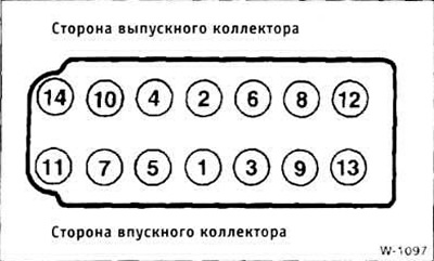
- 2nd pass - tighten bolts in sequence 1-10 by 90±5°, bolts 11-14 by an angle of 73±3° (see W-1097). 15 minutes engine warm-up.
- 3rd pass - tightening with a rigid key at an angle of 90±5°.
This article is available at russian, bulgarian, belarusian, ukrainian, serbian, croatian, romanian, polish, slovak, hungarian
Article verified: Polikarpov Saveliy
Share information:
Previous articles
БМВ E30: M10/M20 engine
Next articles
Similar articles on other types of BMW cars:
Removal and installation of cylinder head — engines M20, M21, M30 BMW 5 Series E34 (1988-1996)
Removal and installation the cylinder head / replacing the cylinder… BMW 5 Series E39 (1995-2003)
Cylinder head of gasoline engines of the M52 series — removal and… BMW 7 Series E32 (1986-1994)
Removal and installation cylinder head covers BMW 7 Series E38 (1994-2001)
Removal and installation the cylinder head BMW X3 E83 (2003-2010)
Removal and installation the lock cylinder BMW X5 E53 (1999-2006)
Link in different formats to this page
Visitor comments
No comments yet
- General information
- Manual
- Maintenance
- Power unit
- Engine repair
- Cooling system
- Power system (gasoline)
- Injection system (gasoline)
- Fuel system (diesel)
- Exhaust system
- Ignition system
- Charge and launch systems
- Transmission
- Car gearbox
- Clutch and drive shafts
- Chassis
- Brake system
- Suspension front and rear
- Steering
- Body
- Body care and repair
- Exterior
- Interior
- Electrical equipment
- Troubleshooting
- Lighting and signaling
- Equipment and devices
- Heater and air conditioner
- Electrical circuits
- General information
- Manual
- Repair on the road
- Weekly checks
- Maintenance
- Troubleshooting
- Power unit
- 4 cylinder engines
- 6 cylinder engines
- Engine overhaul
- Cooling and heating
- Fuel and exhaust system
- Starting and charging system
- Ignition system
- Transmission
- Clutch
- Mechanical gearbox
- Automatic gearbox
- Cardan and drive shafts
- Chassis
- Brake system
- Wheel suspension
- Steering
- Body
- Exterior
- Interior
- Electrical equipment
- Equipment and devices
- Electrical circuits
- General information
- Maintenance
- Power unit
- Engine repair
- Cooling system
- Ignition system
- Supply system
- Fuel injection system
- Exhaust system
- Transmission
- Clutch
- Car gearbox
- Front and rear axle
- Chassis
- Steering
- Brake system
- Body
- Exterior
- Interior
- Electrical equipment
- Heating system
- Equipment and devices
- Power devices
- Electrical circuits
- Power unit
- M10/M20 engine
- M40 engine
- Ignition system
- Lubrication system
- Cooling system
- Supply system
- Fuel injection
- Exhaust system
- Transmission
- Clutch
- Manual gearbox
- Front axle
- Rear axle
- Chassis
- Steering
- Brake system
- Body
- Exterior
- Interior
- Electrical equipment
- Heating system
- Equipment and devices
- Electrical circuits
- General information
- Specifications
- Operation and maintenance
- 4-cylinder engine
- Engine repair
- Cooling and lubrication system
- Supply system
- Ignition system
- 6-cylinder engine
- Engine repair
- Cooling and lubrication system
- Supply system
- Fuel injection system
- Ignition system
- Transmission
- Clutch
- 4-speed manual gearbox
- 5-speed manual gearbox
- Automatic gearbox
- Cardan and rear axle
- Chassis
- Steering
- Front suspension
- Rear suspension
- Brake system
- Electrical equipment
- Equipment and devices
- Electrical circuits