
Table of contents: Removal ↓ Installation ↓
- Home
- BMW 7 Series
- E32
- Power unit
- Minor engine repair
- Cylinder head of gasoline engines of the M52 series — removal and installation
Cylinder head of gasoline engines of the M52 series — removal and installation (BMW 7 Series E32)
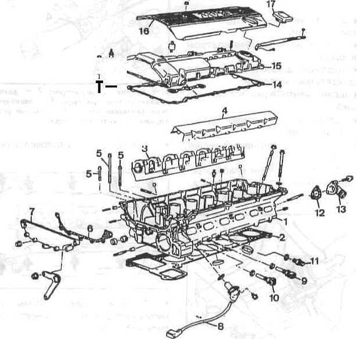
Elements of the cylinder head of the M52 engine
1 - cylinder head;
2 - cylinder head gasket;
3 — camshaft bearing housings;
4 — protective cover of the intake camshaft;
5 — cylinder head mounting bolt;
6 - gasket;
7 - side cover;
8 — intake camshaft angular position sensor;
9 - coolant temperature sensor;
10 — fan switch sensor;
11 — nipple;
12 — gasket;
13 — coolant outlet pipe;
14 - Cylinder head cover gasket;
15 - cylinder head covers;
16 - decorative cover;
17 — oil filler plug.
Removal
Disconnect the ground cable from the battery.
Note: This will erase information about faults in electronic memory devices.
Raise the car.
Unscrew the front muffler pipe from the exhaust manifold.
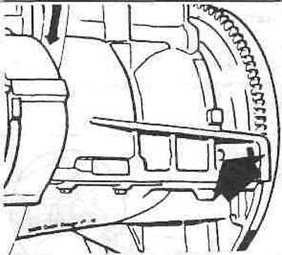
Drain the coolant from the engine by unscrewing the drain plug on the side of the engine block under the exhaust manifold.
Disconnect the water hoses from the thermostat, after loosening the clamps.
Disconnect the throttle cable from the throttle lever.
Remove the oil filler cap.
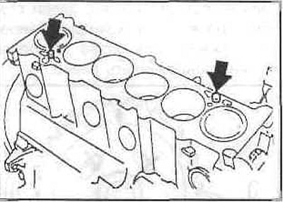
Remove the small plugs with a screwdriver and unscrew the bolts located underneath. Remove the two plastic covers from the cylinder head.
Unscrew the ground jumper from the front side of the cylinder head.
Disconnect the cylinder head ventilation nipple, while lifting the bar on the nipple with a screwdriver.
Loosen the bolt and remove the sensor from the cylinder head.
Unscrew the two bolts and remove the shoe. Mark the position of the rubber gaskets for subsequent installation.
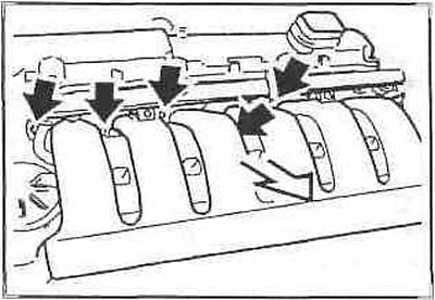
On each ignition coil, pull up the metal bracket and disconnect the connector. Remove the connector block along with the wires.
Unscrew the ignition coils and remove them. Mark the position of the ground jumpers for subsequent installation.
Disconnect the following hoses and connectors from the throttle body pipe, having previously marked them and their mounting locations. Having loosened the hose clamps, remove the connector fixing brackets:
- throttle switch connector;
- air temperature sensor connector;
- throttle body heating water hoses;
- fuel tank ventilation hose;
- fuel supply hose (white nipple);
- return fuel hose (black nipple).
Disconnect the idle air control valve hose from the bottom of the intake manifold.
Caution: The locking tabs are easily broken.
Unscrew the intake pipe support.
Disconnect the intake manifold from the cylinder head.
While pressing the wire clips, disconnect the connectors.
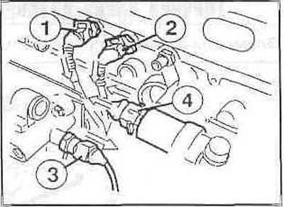
1 - temperature sensor;
2 - temperature indicator sensor;
3 - oil pressure switch;
4 — idle speed control valve.
Remove the cylinder head cover.
Pull back the side clips to remove the cable channel from the front of the thermostat.
Unscrew the casing.
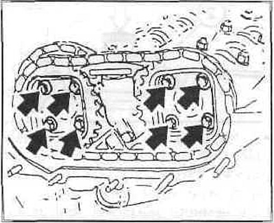
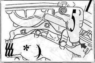
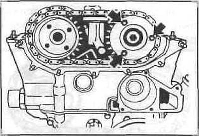
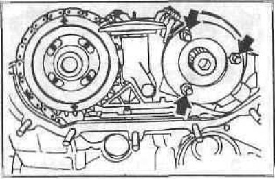
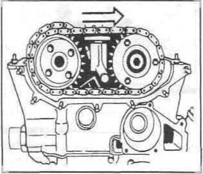
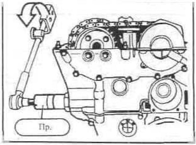
Set the piston of the first cylinder to the top dead center position. To do this, engage fifth gear and turn the crankshaft pulley in the direction of engine rotation to a position in which the camshaft cams of the intake and exhaust valves of the first cylinder (from the drive chain side) will be facing each other. In this case, the arrows on the sprockets of both camshafts should point upwards.
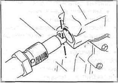
Fix the crankshaft at top dead center by inserting a rod through the hole in the engine block into the hole in the flywheel.
Early model years
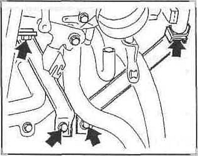
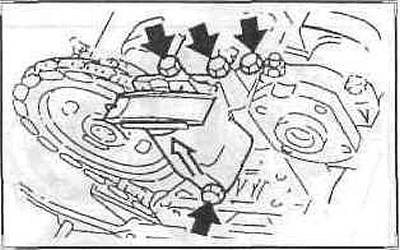
Remove the lifting eye and the upper gear case cover. Mark the position of the centering bushings of both outer bolts for subsequent installation. Remove the gasket, which must be replaced.
Remove both valve cover mounting bolts.
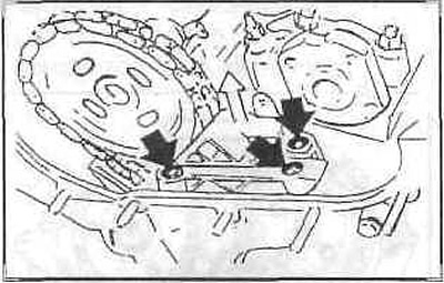
Press the upper chain tensioner and secure it in this position with the device.
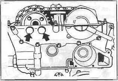
After unscrewing the mounting bolts, remove the chain sprockets together with the chain.
Late model years (with VANOS)
Unscrew the oil pipe of the VANOS actuator and plug it with a plug.
Disconnect the VANOS actuator solenoid valve connector.
Unscrew the plugs from the actuator.
Loosen the bolts securing the exhaust camshaft sprocket.
Press the upper chain tensioner and secure it in this position with the device.
After unscrewing the fastening nuts, remove the VANOS actuator unit.
Unscrew the bolts securing the intake camshaft sprocket. Remove the spacer washer from the sprocket.
Remove both sprockets from the camshafts along with the chain.
Remove the upper chain tensioner bracket.
Remove the tensioner from the cylinder head.
Caution: Hold the tensioner, it is under spring action.
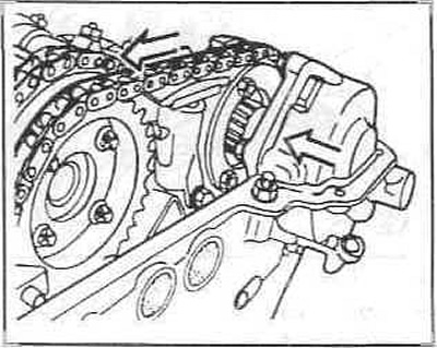
Remove the chain guide and exhaust camshaft sprocket.
Caution: Secure the chain to the wire to prevent it from falling.
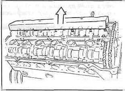
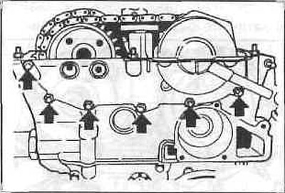
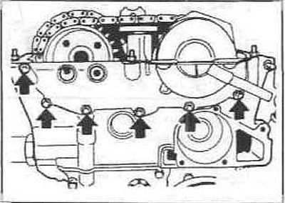
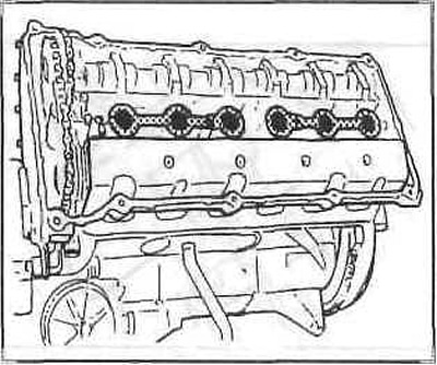
In several steps, from the inside out, unscrew the cylinder head bolts and remove the head.
Installation
Check the integrity and correct installation of the centering bushings.
Fix the camshafts in the correct position with a tool. If necessary, turn the camshafts using the 24 mm Allen keys.
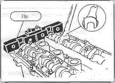
Caution: Do not damage the camshafts.
In this case, the camshaft must be installed so that the valves of the 1st and 6th cylinders move, to do this, first turn the crankshaft approximately 30° from the top dead center position and only then turn the camshaft back. This prevents the valves from touching the pistons.
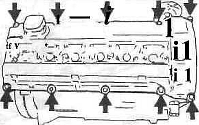
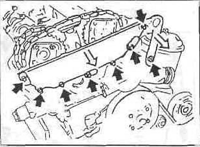
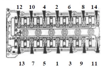
Tighten the cylinder head bolts in three steps each time in sequence 1 through 14.
- Step 1: Tighten the bolts in sequence 1 to 14 using a torque wrench to a tightening torque of 30 Nm.
- Step 2: Tighten the bolts with a hard wrench to 90°.
- Step 3: Tighten the bolts with a hard wrench to 90°.
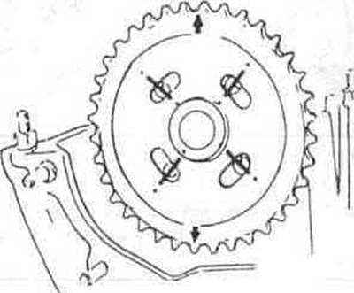
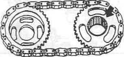
Place the sprocket on the camshaft flange. The arrow on the sprocket should point upwards. The threaded holes should be on the left side of the slots, as the sprocket should turn to the left when installing the tensioner.
Install the chain guide and upper chain tensioner.
Early model years
Install the top chain with sprockets, the arrows on the sprockets should point upwards. Do not tighten the sprocket bolts yet.
Late model years (with VANOS)
Screw the device into the tensioner thread. The device presses on the chain and slightly tightens it so that the camshaft sprockets are installed in the middle of the slots. With some experience, you can make such a device yourself. Without the device, correct installation of the chain is impossible.
Insert the spacer washer and tighten the bolts to 20 Nm.
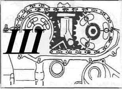
Install the top chain with sprockets, with the flat side of the intake camshaft sprocket facing outward and the lug facing the camshaft.
The arrow on the exhaust camshaft sprocket should point upwards. The bolts should be positioned in the middle of the slots.
Place the spacer washer on the intake camshaft and tighten.
Secure the exhaust camshaft sprocket without tightening the bolts.
Before installing the VANOS adjustment unit, turn both sprockets in the slots to the right as far as they will go.
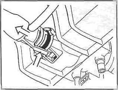
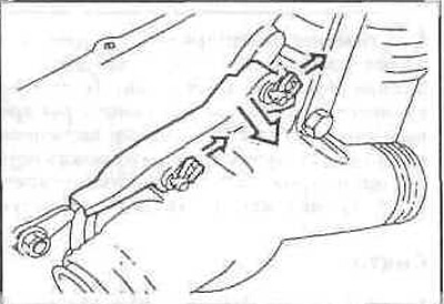
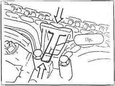
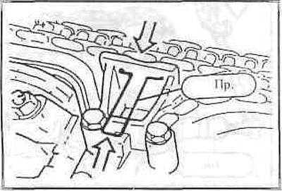
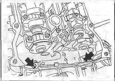
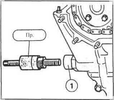
Before installation, press back the VANOS toothed shaft with the hydraulic piston (1) until it stops in the direction of the housing (2).
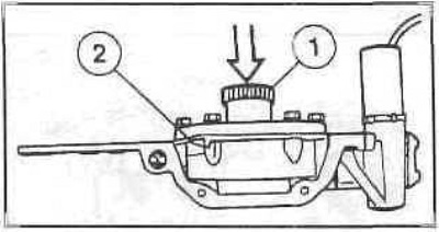
Install the VANOS adjustment unit so that the toothed shaft engages with the sprocket. If necessary, turn the sprocket slightly counterclockwise so that the toothed shaft engages. Move the VANOS adjustment unit towards the cylinder head so that the sprocket turns to the left.
Screw on the VANOS adjustment unit. Cover the joint surfaces between the cylinder head and the VANOS adjustment unit with sealant.
Tighten the tensioner by turning the tensioning bolt of the device with a tension force of 1.3 Nm.
In this position, tighten the exhaust camshaft sprocket bolts evenly in two steps to 20 Nm.
Remove the camshaft locking and chain tensioning tool.
Secure the VANOS oil pipe with new gaskets. Connect the electrical connector.
Secure the lower tensioner with a new ring using a tightening torque of 35 Nm. The slot must be vertical.
Early model years
Tighten the sprocket bolts crosswise to 20 Nm.
Install the upper gearbox cover with a new gasket. Tighten the M6 bolts to 10 Nm and the M8 bolts to 22 Nm. Place bushings on both outer bolts.
Screw in the two valve cover bolts.
Remove the camshaft holding device.
Install the cylinder head cover and intake manifold.
Tighten the cylinder head cover bolts evenly to 10 Nm.
Insert the ignition coils with paper gaskets and secure them.
Connect the ignition coil connectors and secure them with metal brackets.
This article is available at russian, bulgarian, belarusian, ukrainian, serbian, croatian, romanian, polish, slovak, hungarian
Article verified: Sevastyanov Nikolay
Share information:
Previous articles
БМВ E32: Minor engine repair
Next articles
Similar articles on other types of BMW cars:
Removal and installation the cylinder head. Models 320i, 325i, 328i… BMW 3 Series E36 (1990-2000)
Removal and installation the cylinder head BMW 3 Series E30 (1982-1994)
Removal and installation of cylinder head — engines M20, M21, M30 BMW 5 Series E34 (1988-1996)
Removal and installation the cylinder head / replacing the cylinder… BMW 5 Series E39 (1995-2003)
Removal and installation the cylinder head BMW X3 E83 (2003-2010)
Removal and installation the lock cylinder BMW X5 E53 (1999-2006)
Link in different formats to this page
Visitor comments
No comments yet
- General information
- Introduction to guide
- Manual
- Maintenance
- Power unit
- Engine M60/1, M60/2 (petrol)
- M62 engine (petrol)
- M57 engine (diesel)
- M67 engine (diesel)
- Cooling system
- Fuel system (petrol)
- Fuel system (diesel)
- Exhaust system
- Ignition and control systems
- Charge and launch systems
- Transmission
- Clutch
- Mechanical gearbox
- Automatic gearbox
- Cardan and drive shafts
- Chassis
- Brake system
- Front suspension
- Rear suspension
- Steering
- Body
- Exterior
- Interior
- Electrical equipment
- Equipment and devices
- Lighting
- Heating and air conditioning
- Electrical circuits
- General information
- Care and maintenance
- Power unit
- Minor engine repair
- Engine overhaul
- Lubrication system
- Cooling system
- Ignition system
- Supply system
- Injection system (petrol)
- Injection system (diesel)
- Exhaust system
- Transmission
- Clutch
- Manual gearbox
- Automatic gearbox
- Cardan gear
- Rear axle and shafts
- Chassis
- Front suspension
- Rear suspension
- Steering
- Wheels and tires
- Brake system
- Body
- Body elements
- Electrical equipment
- Equipment and devices
- Electrical circuits