
Attention:
- Alloys of aluminum and magnesium. The use of steel bolts is prohibited. Danger of electrochemical corrosion.
- For magnesium housings, use only aluminum screws.
- After unscrewing, aluminum bolts must be replaced.
- To ensure identification of aluminum bolts, the ends of their heads are painted blue.
- Strictly observe the tightening torque and angle (danger of damage).
1. Remove the exhaust system.
2. Drain the coolant.
3. Drain the engine oil.
4. Remove both exhaust manifolds.
5. Remove the intake manifold.
6. Disconnect the coolant hoses from the cylinder head.
7. Remove the intake and exhaust actuators.
Attention:
- Replace the cylinder head bolts.
- Do not wash off the coating from the bolts.
- There should be no coolant, water or engine oil in the blind holes.
- Risk of corrosion and cracking.
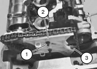
8. Remove the screws (1).
9. Disconnect the drive chain module (3) at the connection (2) and remove it with an upward movement.
10. Remove the drive chain from the sprocket.
Attention:
- If the timing chain is removed from the sprocket, the crankshaft can no longer be turned.
- The result may be jamming or jumping of the drive chain on the crankshaft sprocket.
Note: The chain can only be pulled out when installed using the hook.
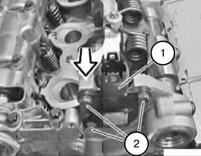
11. Loosen the bolts (2) securing the eccentric shaft sensor (1).
12. Remove the eccentric shaft sensor (1) forward.
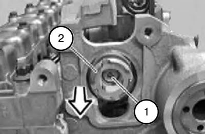
Caution: The screw (1) is non-magnetic and must be protected from falling.
13. Unscrew the screw (1).
14. Remove the magnetic wheel (2) forward.
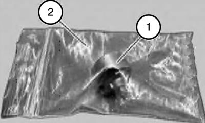
Caution: The magnetic wheel (1) is highly magnetized and must therefore be protected from metal filings.
15. After removal, place the magnetic wheel (1) in a plastic bag (2) with a lock.
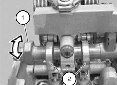
16. Install the eccentric shaft (1) with preload in the direction indicated by the arrow, moving upwards.
17. Remove the stop screw between the 1st and 2nd cylinders.
Tightening torque: 10 Nm.
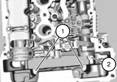
Note: Bolt (2) can only be loosened when the chain module is pressed slightly forward.
Caution: Grasp the bolt (2) with pliers to prevent it from falling.
18. Unscrew the screw (2).
Tightening torque: 10 Nm + 90°.
19. Remove the screws (1).
Tightening torque: 10 Nm + 135°.
Note: Aluminum bolts must be replaced during installation.
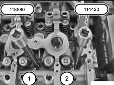
Note: Pay attention to the different bolt heads.
20. Unscrew the bolts (1) securing the M10 cylinder head using tool 118580.
21. Unscrew the bolts (2) securing the M9 cylinder head using tool 114420.
Note: Intake and exhaust camshafts are not shown in the illustration.
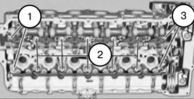
Attention. Pay attention to the different lengths of bolts (1 and 3) M9.
22. Unscrew the bolts (1 and 3) securing the cylinder head M 9 using tool 114420.
Tightening torque: 30 Nm + 90° + 45°.
23. Unscrew the bolts (2) securing the cylinder head M 10 using tool 118580 from the edges to the middle.
Tightening torque: 30 Nm + 90° + 90° + 45°.
Attention:
- All cylinder head mounting bolts (1, 2 and 3) must be replaced.
- Strictly observe tightening torques and angles.
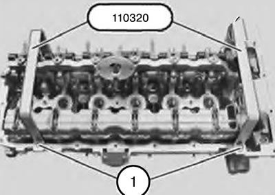
24. Secure tool 110320 with the existing cylinder head cover mounting bolts (1).
Tightening torque: 9 Nm.
Attention:
- Remove and install the cylinder head only with an assistant.
- The weight of the cylinder head with additional elements is approximately 40 kg.
- Do not place the cylinder head on the sealing surface. Risk of damage to injectors.
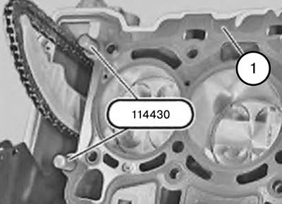
25. Insert tool 114430 into the cylinders.
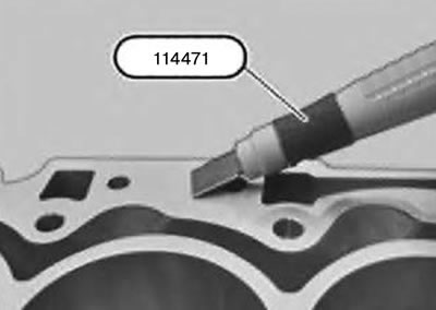
26. Remove large remains of sealant using tool 114471 from the sealing surfaces of the cylinder head and crankcase.
Caution: Do not use a chip removal tool.
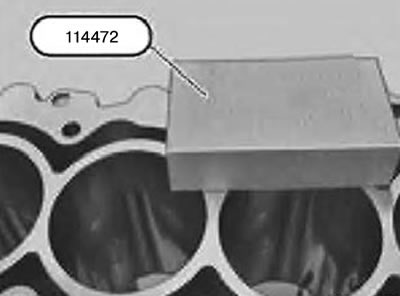
27. Remove small residues of sealant using tool 114472 from the sealing surfaces of the cylinder head and crankcase.
Attention:
- Do not use a chip removal tool.
- There should be no coolant, water or engine oil in the blind holes.
- Risk of corrosion and cracking.
28. Clean all blind holes.
29. Replace the cylinder head gasket.
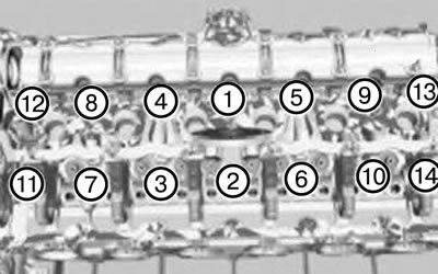
Caution: Strictly follow the tightening sequence of the cylinder head bolts.
30. Replace the cylinder head mounting bolts.
31. Insert the cylinder head mounting bolts (1-10) using tool 118580.
Tightening torque: 30 Nm + 90° + 90° + 45°.
32. Insert the cylinder head mounting bolts (11-14) using tool 114420.
Tightening torque: 30 Nm + 90° + 45°.
Note: Intake and exhaust camshafts are not shown in the illustration.
Caution: Strictly follow the tightening sequence of the cylinder head bolts.
Attention:
The 2nd tightening angle applies to the cylinder head mounting bolts (1-10).
When installing:
- Tightening torque: Tighten all cylinder head bolts (1-14) to 30 Nm.
- 1st tightening angle: Tighten all cylinder head mounting bolts (1-14) to an angle of 90°.
- 2nd tightening angle: Tighten only the cylinder head mounting bolts (1-10) to an angle of 90°.
- 3rd tightening angle: Tighten all cylinder head bolts 1-14 at an angle of 45°.
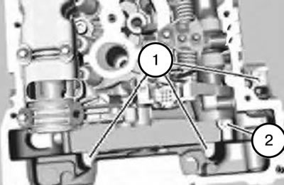
33. Insert bolts (1).
Tightening torque: 10 Nm + 135°.
Caution: Grasp the bolt (2) with pliers to prevent it from falling.
34. Insert the bolt (2).
Tightening torque: 10 Nm + 90°.
Note: Aluminum bolts must be replaced during installation.
35. Assemble the engine.