
6-cylinder petrol engine
Note: This section describes the removal and installation of the cylinder head of the M52 engine installed in vehicles up to 8/97. Instructions for the M52TU engine installed from 9/97 onwards are provided at the end of the chapter.
A defective cylinder head gasket is determined by one or more of the following signs:
- Loss of power.
- Loss of coolant. White exhaust gases when the engine is warm.
- Loss of oil.
- The presence of coolant in the engine oil, the oil level does not decrease, but it becomes less.
- Gray color of engine oil, foam emulsion on the oil level indicator, liquid oil.
- Engine oil in coolant.
Note: In this case, after the repair, it is necessary to remove the radiator and wash it using a BMW cleaning agent to remove any remaining oil.
The coolant is bubbling violently.
There is no compression in two adjacent cylinders.
Removal
The cylinder head should only be removed from a cooled engine. Do not remove the exhaust and intake manifolds from the head.
Disconnect the negative (-) battery cable. The battery is located in the luggage compartment behind the right side trim.
Caution: This will erase the contents of memory devices, such as the engine fault code memory. Follow the instructions in Chapter "Removal and installation the battery".
Raise the car.
Unscrew the front exhaust pipe from the exhaust manifold, see page 66.
Drain the coolant, see the distribution "Maintenance work".
Drain the coolant from the engine by unscrewing the drain plug on the side of the cylinder block under the exhaust manifold. After draining, immediately screw the plug back in place and tighten.
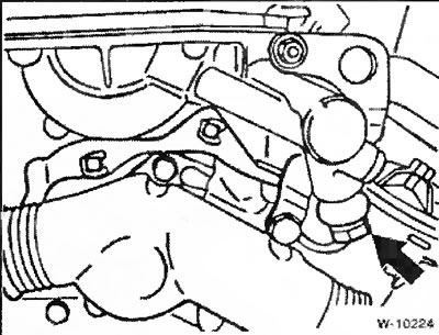
Loosen the clamps and remove the coolant hoses from the thermostat.
Remove the spark plugs, see section "Maintenance work".
Remove the intake manifold.
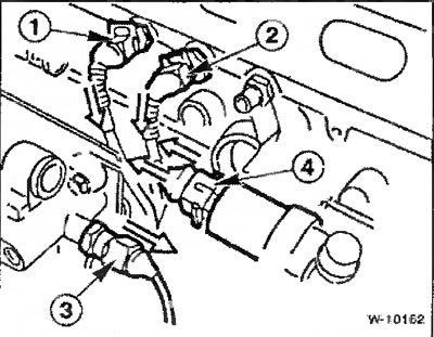
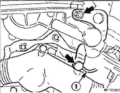
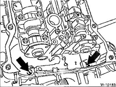
Squeeze the wire stoppers and disconnect the plug connectors:
- 1 - temperature sensor,
- 2 - remote thermometer,
- 3 - hydraulic switch,
- 4 - valves for regulating the crankshaft speed at idle speed.
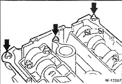
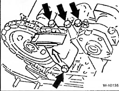
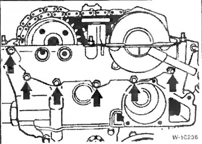
Unscrew the bolts securing the cylinder head cover "arrows". Pay attention to the location of the rubber pads under the bolts for subsequent assembly.
Remove the side clips and remove the wire routing box from the thermostat housing.
Remove the intake camshaft cover.
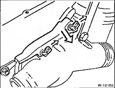
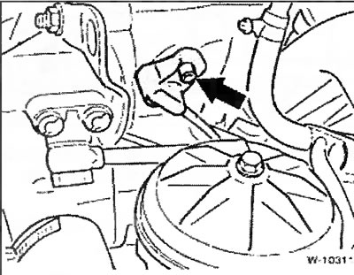
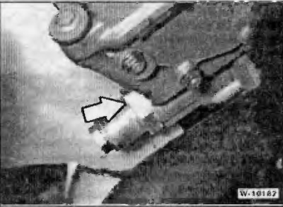
Unscrew the fastening of the eye for hanging the "arrow" engine.
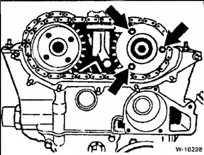
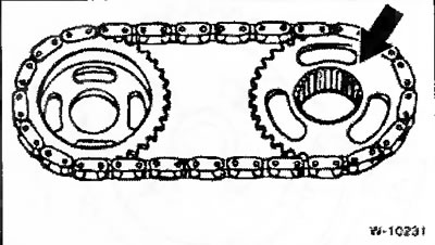
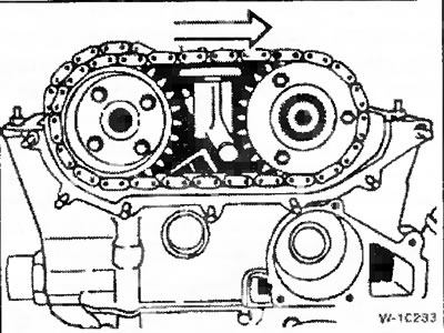
Place the engine crankshaft in a position where the piston of cylinder 1 is at TDC, while the tops of the cams of the intake and exhaust camshafts for cylinder 1 (from the camshaft drive chain side) must be equally directed upwards. The arrows on the sprockets of both camshafts must be directed upwards. The crankshaft can be turned in different ways:
- engage 5th gear and roll the car forward on a level surface or
- turn the crankshaft belt pulley with a socket wrench by the central mounting bolt in the direction of rotation (with neutral gear engaged.
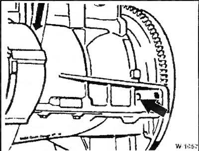
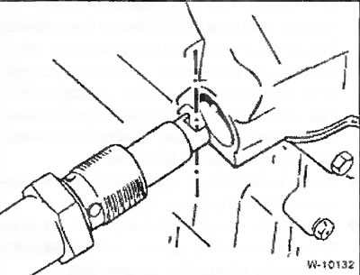
Fix the engine crankshaft in the TDC position for cylinder 1 using the BMW 112 300 tool or another suitable pin. To do this, remove the plug and insert the pin through the hole in the cylinder block into the hole in the flywheel.
Unscrew the oil line from the VANOS actuator and close the holes with clean plugs.
Disconnect the electrical connector from the VANOS actuator solenoid valve.
Unscrew the studs.
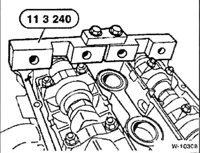
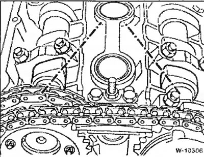
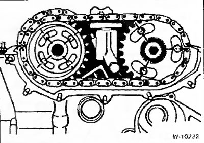
Lock the camshafts in the TDC position for cylinder 1 using the BMW device shown in the figure. If necessary, tighten the camshafts further using the Allen key SW24.
Caution: Do not damage the camshaft housing. If necessary, mill the key to make it narrower.
If the camshafts need to be turned so much that the valves of cylinders 1 and 8 are set in motion, the crankshaft must first be turned from the TDC position in the direction of rotation by approximately 30° and only after turning the camshafts should it be returned back. This avoids contact between the valves and the pistons.
Unscrew the plugs from the actuator housing.
Loosen the exhaust camshaft sprocket mounting bolts.
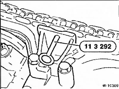
Press the upper chain tensioner down and fix it in this position using a special device from BMW.
Loosen the nuts and remove the cover.
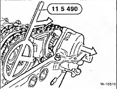
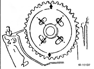
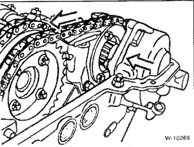
Remove the VANOS actuator and turn the sprockets all the way to the right. If the sprockets do not turn by hand due to the installed disc spring, a special BMW device should be attached to one sprocket to increase the turning force, as shown in the figure.
Loosen the cylinder identification sensor fastening. Disconnect the sensor plug connector.
Loosen the intake camshaft sprocket mounting bolts. Remove the adjusting washer from the sprocket.
Remove both sprockets together with the chain from the camshafts.
Remove the upper chain tensioner support bracket.
Unscrew the chain tensioner at the cylinder head.
Caution: Hold the tensioner as it is under the action of the spring.
Remove the chain guide and then the sprocket from the exhaust camshaft.
Note: To prevent the chain from slipping down, use a wire hook.
Installation
Before installation, clean the contact surfaces of the cylinder head and block using a standard sealant remover and a suitable wooden scraper. Make sure that sealant residue does not get into the holes, for which purpose cover the holes with rags.
The cylinder block holes for the cylinder head bolts should be thoroughly cleaned of oil and other deposits using compressed air or a rag wrapped around a thin screwdriver.
Caution: There must be no oil in the blind holes, otherwise the bolts will not be able to tighten the cylinder head to the required force, although they will be tightened to the prescribed torque value. In addition, the cylinder block may crack in this case.
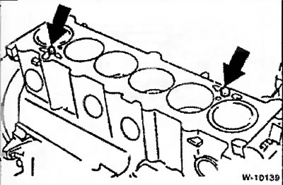
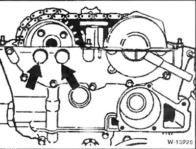
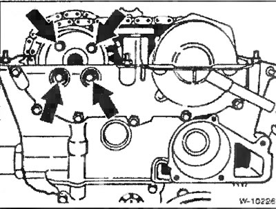
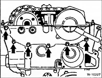
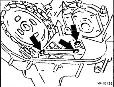
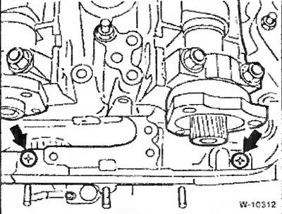
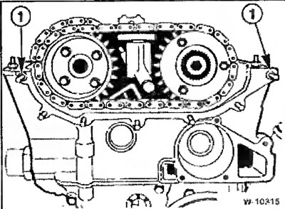
Check the guide bushings "arrows" in the cylinder block for damage and correct installation. The bushings serve to center the cylinder head.
Check the cylinder head for cracks and make sure there are no marks on the working surface of the cylinders.
Check the cylinder head and cylinder block for straightness in the longitudinal and transverse directions using a steel ruler. If necessary, perform finishing of the parts (workshop work). The maximum permissible non-linearity is 0.03 mm.
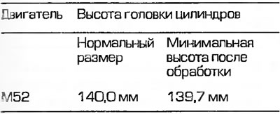
Note: In case of a machined cylinder head, depending on the height of the head after processing, a sealing gasket of either normal thickness or increased thickness, which is 0.3 mm thicker than normal, can be installed. A thicker gasket avoids reducing the volume of the combustion chamber.
Seal the transitions to the sprocket niche cover with Drei Bond 1209 sealant, which retains elasticity for a long time.
The cylinder head gasket must be installed. The cylinder head gasket must be placed with the rip and on the dry surface of the cylinder block so that the holes in the head and cylinder block are not covered.
The camshafts must be secured in the correct position using the BMW W-1030B device shown in the figure.
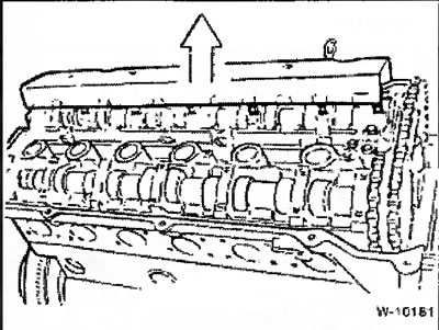
Together with an assistant, place the cylinder head, avoiding any distortion, since otherwise the new sealing gasket will be damaged.
Caution: Always use new cylinder head bolts. New bolts can be easily lubricated with engine oil during installation. The washers under the bolt heads of the serial cylinder head do not fall out, as they are caulked. When installing a new cylinder head, insert new washers without caulking.
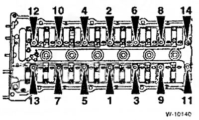
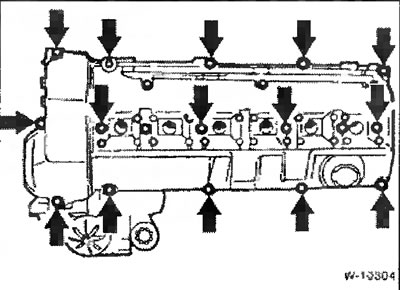
Tighten the cylinder head bolts in sequence from 1 to 14 in three steps:
- Method 1: using a torque wrench with a torque of 40 Nm.
- Method 2: Using the locked key, turn it to an angle of 90°.
- Step 3: Using the locked key, turn it to an angle of 90°.
Caution: The cylinder head bolts must be tightened very carefully. Before tightening, the torque wrench must be checked for accuracy. In addition, a protractor, such as the HAZET 6690, is required to tighten the cylinder head bolts. If a protractor is not available, the torque wrench is placed on the bolt head, a right-angle ruler is placed against the wrench lever, and a mark corresponding to a 90° turn of the wrench is made on the cylinder head with a small ruler. Then, with one force, the handle of the wrench is turned until it aligns with the mark.
Tighten the sprocket housing cover mounting bolts.
Place the sprocket on the camshaft flange. The arrow on the sprocket should point upwards. The threaded holes on the camshaft flange should be located on the left side of the longitudinal slots for the bolts on the sprocket, since when installing the chain tensioner, the sprocket turns to the left.
Install the chain guide and upper chain tensioner.
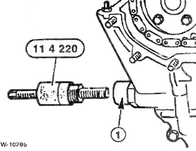
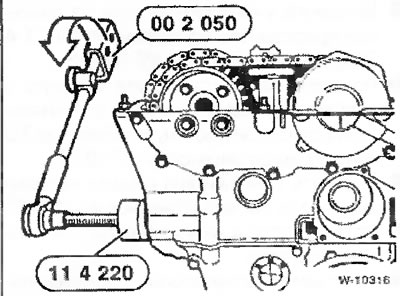
Screw the special tool from BMW 11 4220 into the threaded hole "1" for the chain tensioner.
This device presses on the camshaft drive chain and is pre-tensioned so that the threaded holes in the shaft flanges are located in the middle of the longitudinal slots in the sprockets. With some skill, a similar device can be made independently. Without the device, correct installation of the camshaft drive chain is impossible.
Install the adjusting washer on the intake camshaft and tighten it to 20 Nm.
Place the sprockets on the camshaft flanges together with the upper camshaft drive chain. The flat side of the intake camshaft sprocket should face outward and its shoulder should face the camshaft.
The arrow on the exhaust camshaft sprocket points upward. The sprocket mounting bolts should be located in the middle of the longitudinal slots in the sprocket.
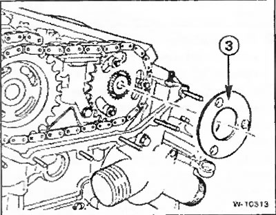
Execution of the disc spring base: attach the adjusting washer "3" to the intake camshaft sprocket and tighten the fastening with a torque of 20 Nm.
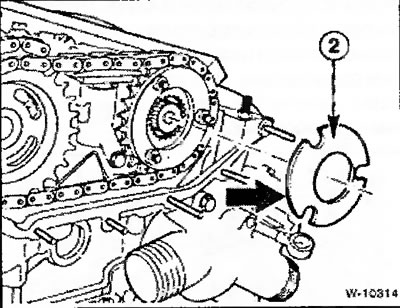
Version with disc spring: place the adjusting washer on the intake camshaft sprocket (approximately 2 mm thick), then install the disc spring "2".
Attention. Ensure the correct mounting position of the disc spring. The larger diameter of the spring should be adjacent to the camshaft sprocket. Then install the adjusting washer (approximately 4 mm thick). Apply a non-loosening agent to the 3 fastening nuts and tighten the nuts to a torque of 20 Nm.
Tighten the exhaust camshaft sprocket, but do not tighten the bolts too much.
Before installing the VANOS actuator, turn both sprockets to the stop (as far as the longitudinal slots in the sprockets allow) to the right.
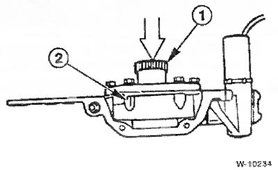
Before installing the VANOS actuator, press its splined shaft with hydraulic piston "1" all the way into the mechanism housing "2".
Ensure the correct position of the guide bushings "1". Seal the corner joints of the sealing surfaces between the mechanism housing and the cylinder head with liquid sealant Drei Bond 1209.
Insert the VANOS actuator so that the spline shaft of the actuator is fixed in the sprocket. To ensure that it is fixed, turn the sprocket counterclockwise by hand (or with a tool for the version with a disc spring).
Note: Fixation must be performed with the first tooth, otherwise the valve timing will be shifted.
Move the VAIMOS actuator towards the cylinder head, while the sprocket, due to the helical spline engagement, turns to the left. Use your hand to help the sprocket turn.
Tighten the VANOS actuator mounting nuts.
Remove special tool 11 3 292 and thereby relieve the upper chain tensioner, see "Removal".
Tighten the timing chain tensioner by turning the tension bolt of the special tool to a torque of 1.3 Nm.
In this position, tighten the exhaust camshaft sprocket evenly in a crosswise manner in 3 steps to a torque of 20 Nm.
Remove the special devices for locking the camshafts and pre-tensioning the drive chain.
Note: After this, the BMW service station will check the functioning of the VANOS system using a special device. If no deterioration in the vehicle's dynamic properties occurs after the installation of the VANOS system, the check can be dispensed with, otherwise you should contact the BMW service station.
Screw the oil line with a new sealing gasket to the VANOS actuator housing. Connect the electrical plug connector.
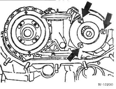
Screw in the lower chain tensioner with a new sealing ring and tighten it to a torque of 35 Nm. Pay attention to the position of the groove on the tensioner piston during installation: the groove should be located vertically in relation to the tensioner bar. When installing, relieve the upper chain tensioner.
Install the sprocket niche cover with a new sealing gasket. Tighten the M6 bolts to 10 Nm and the M8 bolts to 22 Nm. Don't forget about the guide bushings on both outer bolts.
Screw in 3 studs to secure the cylinder head cover.
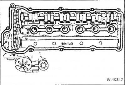
Install the cylinder head cover. Replace damaged gaskets, see figure. When applying the outer sealing gasket of the cylinder head cover, pay special attention to the correct installation of the gasket in the recesses of the cylinder head from its end. Tighten the cover mounting bolts evenly to a torque of 10 Nm.
Insert and screw in the cylinder identification sensor. If the sealing ring is damaged, it should be replaced with a new one.
Install spark plugs, see section "Maintenance work".
Install the intake manifold, see page 10.
Connect the electrical wires, see "Removal".
Screw the front exhaust pipe to the exhaust manifold with a new sealing gasket, see page 66.
Caution: Before starting the engine, remove the locking pin from the hole in the flywheel.
Fill with coolant.
Check the engine oil level and top up if necessary. If the cylinder head was removed due to a defective sealing gasket, it is recommended to replace the oil and oil filter, as the engine oil may contain coolant.