
Table of contents: Removal ↓ Installation ↓
- Home
- BMW 7 Series
- E32
- Power unit
- Minor engine repair
- Cylinder head — removal and installation, gasket replacement
Cylinder head — removal and installation, gasket replacement (BMW 7 Series E32)
Removal
On engines equipped with fuel injection, relieve the fuel system pressure.
Disconnect the ground cable from the battery. If the battery is located in the engine compartment, remove it.
Remove the air filter assembly.
Disconnect the electrical wiring from the distributor (if necessary, label all wires) and high voltage wires from the ignition coil.
Disconnect the wire from the coolant temperature sensor.
Disconnect the fuel lines from the fuel rail depending on the model.
Drain the cooling system.
Mark and then disconnect all remaining hoses from the throttle body, intake manifold and cylinder head (depending on the model).
Disconnect the gas pedal cable from the throttle linkage.
Disconnect the exhaust manifold from the cylinder head.
On some engines, it may be necessary to disconnect the manifold from the exhaust pipe.
Remove or disconnect any remaining hoses or pipes from the intake manifold, including the vacuum advance hose and the coolant and heater hoses.
Remove the intake manifold. Do not disconnect or remove any fuel injection system components unless absolutely necessary.
Remove the fan drive belt and the fan itself.
Remove the valve cover and gasket. Where present, remove the separate semi-circular rubber seal fitted to the front of the cylinder head.
Set the piston of the first cylinder to TDC in the compression stroke. Remove the drive chain.
Note: To speed up the process, you can remove the camshaft sprocket without removing the chain and tie it to the body with a piece of wire. Make sure the wire maintains chain tension, otherwise the chain may slip off one of the sprockets.
Loosen the cylinder head bolts a quarter turn in the reverse order of tightening. Do not disassemble or remove the rocker arm assembly at this stage.
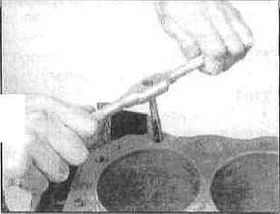
Remove the cylinder head. Do not pry it off with a screwdriver inserted between the head and the cylinder block, as this will
damages the contact surfaces. Instead, insert a blunt rod into the inlet port and gently press the head out.
Remove all remaining external components from the cylinder head. Cylinder head servicing procedures are described in the next section.
Installation
The contact surfaces of the cylinder head and block must be absolutely clean.
Use a scraper to remove all traces of carbon and old sealant, then clean the contact surfaces with a suitable solvent. When working on the block, fill the cylinders with clean rags to prevent dirt from getting inside. Remove the dirt you remove with a vacuum cleaner.
Inspect the contact surfaces of the cylinder block and head for nicks, deep scratches and other damage. If the damage is small, it can be removed with a file; if it is serious, the surface must be re-sanded.
The minimum height of the cylinder head from the contact surface of the valve mechanism cover to the lower contact surface of the cylinder head is 128.6 mm. Thus, a metal layer of up to 0.3 mm can be removed from the surface of the cylinder head compared to the original height. For heads restored in this way, repair gaskets are produced that are 0.3 mm thicker than normal ones. Installing such a gasket will compensate for the decrease in the height of the head. Gaskets are marked for the M30 - 3.0 engine; 3.0E; 3.2E. After grinding the cylinder head, it is necessary to process the end cover.
Clean the bolt holes in the cylinder block with a suitable threaded plug, then blow them out with compressed air. Make sure to remove not only dirt but also oil and water from the holes.
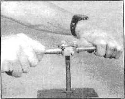
It is recommended to replace the cylinder head bolts, but if you decide to reuse the old ones, clamp each bolt in a vice and run a die over it to remove corrosion and restore the threads. Dirt, corrosion, sealants, and damaged threads will prevent the bolts from being tightened to the proper torque.
If the bolts or their threads are damaged, install a new set of bolts.
Install all components removed from the head prior to cleaning and inspection.
Make sure the mating surfaces of the cylinder head and block are clean. Place the gasket on the cylinder block with the manufacturer's stamp facing up (usually it's the inscription UP, OBEN or something similar). Use the block dowel pins to position the gasket properly.
Carefully install the head onto the cylinder block. Use the dowel pins to position it correctly.
Install the cylinder head mounting bolts.
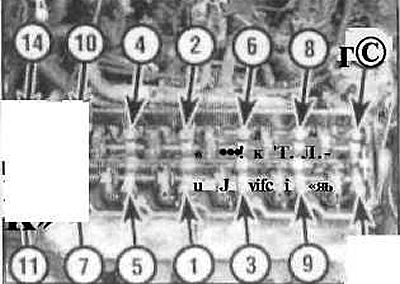
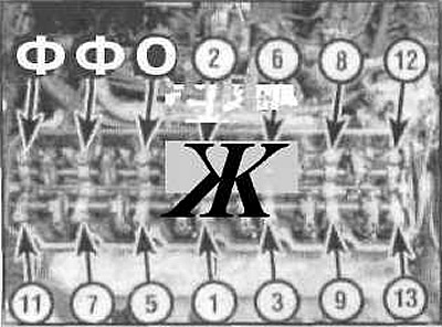
Tighten the cylinder head bolts in the sequence shown to the specified torque in five steps.
- 1st dose - 60 nm puff;
- 2nd step - wait 20 minutes;
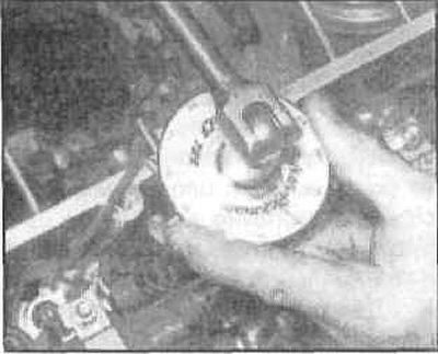
- Step 3: Tighten the bolts by 33°;
- Step 4: Warm up the engine for 25 minutes;
- Step 5: Tighten the bolts by 35°.
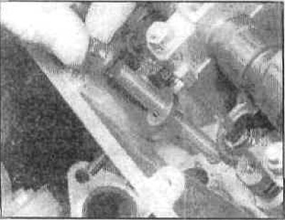
Tightening the bolts to a certain angle
Please note that on engines the final tightening stage is performed after the engine has warmed up to normal operating temperature (i.e. it needs to be launched for some time).
Then install in the reverse order of removal. Before installing the valve cover, adjust the valve clearances (check them again after the engine has warmed up). Start the engine and check the system for leaks.
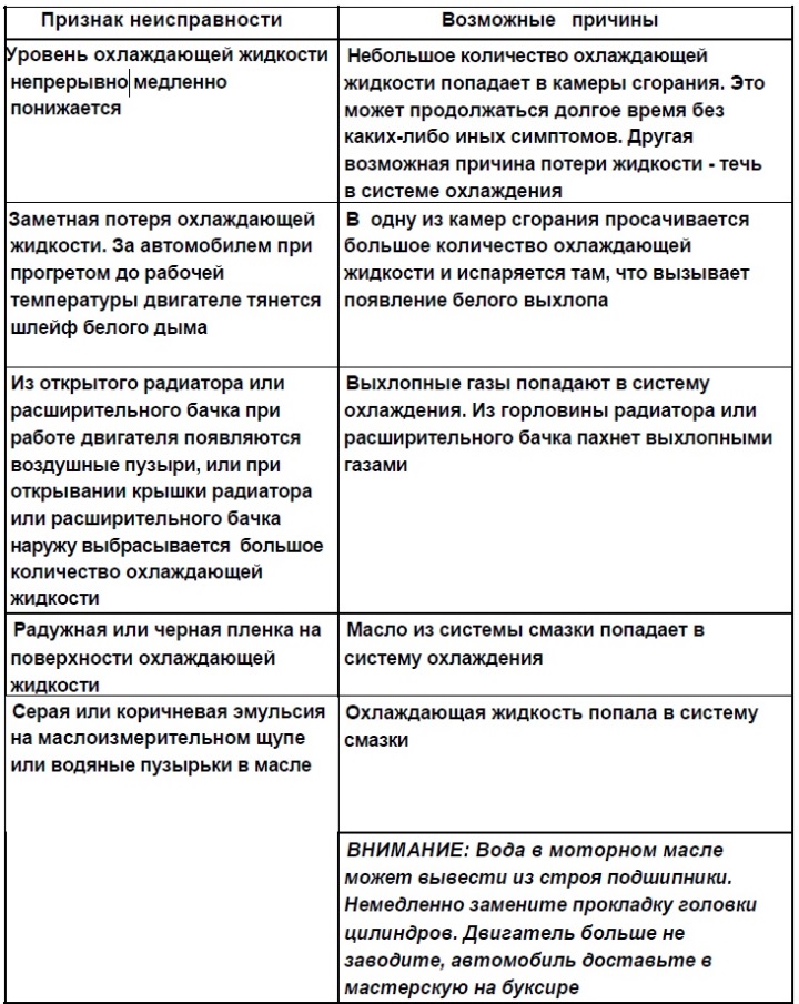
Possible Cylinder Head Malfunctions
This article is available at russian, bulgarian, belarusian, ukrainian, serbian, croatian, romanian, polish, slovak, hungarian
Article verified: Sevastyanov Nikolay
Share information:
Previous articles
БМВ E32: Minor engine repair
Next articles
Similar articles on other types of BMW cars:
Removal and installation the cylinder head / replacing the sealing… BMW 3 Series E46 (1998-2006)
Removal and installation the cylinder head BMW 3 Series E30 (1982-1994)
Removal and installation the cylinder head / replacing the cylinder… BMW 5 Series E39 (1995-2003)
Removal and installation of cylinder head — engines M20, M21, M30 BMW 5 Series E34 (1988-1996)
Removal and installation the cylinder head BMW X3 E83 (2003-2010)
Cylinder head gasket BMW X5 E53 (1999-2006)
Link in different formats to this page
Visitor comments
No comments yet
- General information
- Introduction to guide
- Manual
- Maintenance
- Power unit
- Engine M60/1, M60/2 (petrol)
- M62 engine (petrol)
- M57 engine (diesel)
- M67 engine (diesel)
- Cooling system
- Fuel system (petrol)
- Fuel system (diesel)
- Exhaust system
- Ignition and control systems
- Charge and launch systems
- Transmission
- Clutch
- Mechanical gearbox
- Automatic gearbox
- Cardan and drive shafts
- Chassis
- Brake system
- Front suspension
- Rear suspension
- Steering
- Body
- Exterior
- Interior
- Electrical equipment
- Equipment and devices
- Lighting
- Heating and air conditioning
- Electrical circuits
- General information
- Care and maintenance
- Power unit
- Minor engine repair
- Engine overhaul
- Lubrication system
- Cooling system
- Ignition system
- Supply system
- Injection system (petrol)
- Injection system (diesel)
- Exhaust system
- Transmission
- Clutch
- Manual gearbox
- Automatic gearbox
- Cardan gear
- Rear axle and shafts
- Chassis
- Front suspension
- Rear suspension
- Steering
- Wheels and tires
- Brake system
- Body
- Body elements
- Electrical equipment
- Equipment and devices
- Electrical circuits