
- Home
- BMW 3 Series
- E46
- Power unit
- Engine repair
- Removal and installation the cylinder head / replacing the sealing gasket
Removal and installation the cylinder head / replacing the sealing gasket (BMW 3 Series E46)
The cylinder head can only be removed when the engine is cool. To protect against damage to the paintwork, install protective pads or appropriate covers on the body fenders.
Depending on the engine type, year of vehicle manufacture and equipment, electrical wires, vacuum hoses of coolant may have different routing in the engine compartment. Since it is not possible to consider all design options, it is recommended to mark the corresponding wire with tape before disconnecting it.
Signs of a faulty cylinder head gasket include the following:
1. Drain the coolant, including from the cylinder block, refer to Section Replacing the coolant.
2. Remove the thermostat, refer to Section Removal and installation the thermostat.
3. Remove the intake manifold, refer to Section Removal and installation the intake manifold.
4. Remove the spark plugs, refer to Section Spark plugs.
5. Remove the ignition coils, refer to Section Removal and installation ignition coils/ignition cables.
6. Loosen the mounting bolts and remove the exhaust pipe, refer to Section Removal and installation of the exhaust system.
7. Loosen the mounting bolts and remove the cylinder head cover. First, loosen the bolts evenly crosswise, then unscrew them.
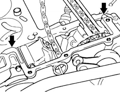
8. Loosen the mounting bolts and remove the air supply device holder and the electromagnetic valve with pressure accumulator (arrows in the illustration).
9. Loosen the mounting bolts and remove the camshaft position sensor and take it out together with the sealing ring.
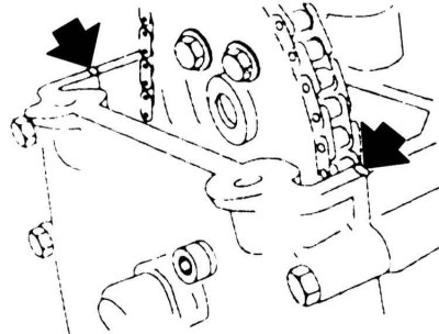
10. Loosen the mounting bolts and remove the upper timing gear box cover. Remove the rubber gasket under the lower cover.
11. Cut from the inside out and remove the cylinder head gasket at the top edge of the lower cover (arrows in the illustration). The gaskets need to be replaced. The gasket for the upper cover of the timing gear box can be used as a spare part.
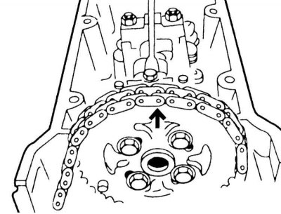
12. Turn the crankshaft by the central mounting bolt to the right so that the piston of the first cylinder is at TDC. In this case, the arrow on the sprocket points up. You can turn the crankshaft in one of the following ways:
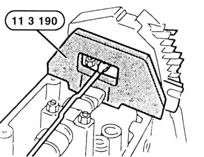
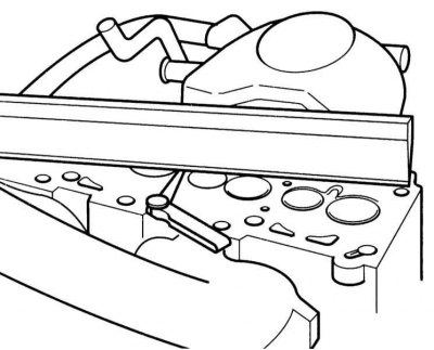
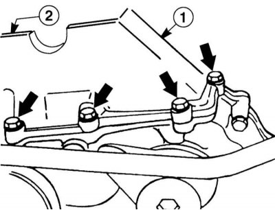
13. Fix the camshafts in this position using the BMW-11 3 190 tool shown in the illustration. You can also use the KLANN tool, KL-0580-5.
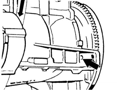
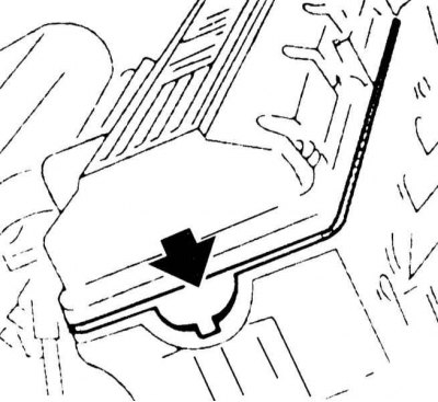
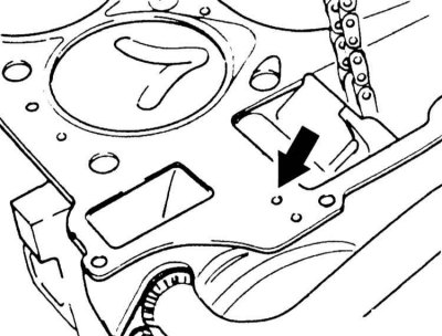
14. Fix the crankshaft in the TDC position with the BMW-11 2 300 tool or a suitable rod. To do this, insert the rod through the hole in the cylinder block into the hole in the flywheel (arrow on the illustration), after removing the plug.
15. Loosen the camshaft sprocket mounting bolts. Slowly push the tensioner shoe back by the hexagon using a wrench and thus relieve the chain. Remove the sprocket.
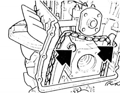
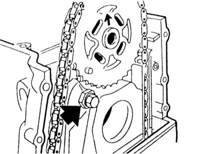
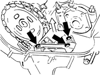
16. Loosen the mounting bolts and remove the damper and tension shoe from the cylinder head (arrows in the illustration).
17. Loosen the cylinder head mounting bolts from the outside inwards in several steps. A special Torx key, such as HAZET-2925, is required to loosen the bolts.
18. Using an assistant, remove the head from the cylinder block.
19. Use a scraper to clean the cylinder block sealing surface from any remaining sealing gasket. Make sure that no dirt gets into the cylinder block openings. Cover the openings with rags.
20. Clean the cylinder head sealing surface.
21. Check the flatness of the cylinder head and block with a steel ruler in the longitudinal and transverse directions. If necessary, treat (work of the service station). Maximum deviation from flatness 0.03 mm. The required cylinder head height is given in the Specifications.
22. Thoroughly clean the threaded holes for the cylinder head mounting bolts from oil and other contaminants.
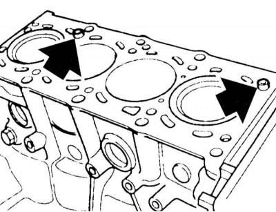
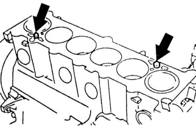
23. Check if there are two guide bushings (arrows in the illustration). If not, insert them and check that they are securely seated.
24. Place a new sealing gasket without sealant on the degreased surface of the cylinder block so that the holes remain open.
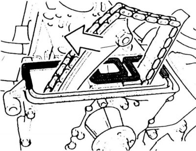
25. Install the cylinder head with the help of an assistant. At the same time, press back the tensioner shoe with a wrench by the Allen key (arrow on the illustration).
26. Lubricate the new cylinder head mounting bolts with engine oil. Then screw the bolts in and tighten them evenly in a spiral from the inside out until they are snug.
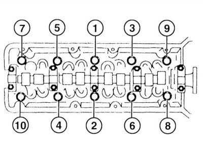
27. Tighten the cylinder head bolts in sequence 1 through 10 in three steps. Tightening torques are given in Specifications.
28. Secure the damper and timing chain tension shoe to the cylinder head.
29. Turn the crankshaft to the TDC position of the first cylinder and insert the rod.
30. Press the tensioner shoe back using the hex key and put on the sprocket with the chain. The arrow on the sprocket should point upwards. Align the oval holes in the center.
31. The camshaft must be fixed at TDC. In this position, secure the sprocket with four bolts to a torque of 10 Nm.
33. Clean the sealing surfaces under the upper timing case cover.
34. Check for damage to the sealing gasket between the upper and lower timing case covers, replace if necessary. Put the gasket down. The raised part of the gasket should fit into the groove on the cylinder head.
35. Replace the timing case cover paper gasket.
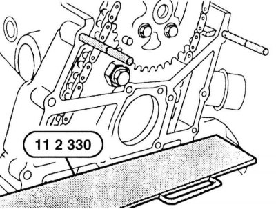
36. Apply a thin layer of grease to the top side of the rubber gasket and the BMW-11 2 330 tool. The tool is placed on the sealing gasket before installing the timing case cover. In addition, two BMW-11 4 110 pins are screwed into the upper threaded holes to guide them. A thin steel sheet and two threaded pins can be used instead of the specified tools.
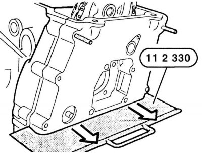
37. Install the timing case cover, insert and screw in the mounting bolts so that the bolt head fits. Remove the BMW-11 2 330 tool.
38. Install the cylinder head cover without the gasket. Screw in the M6 screws with large washers (arrows in the illustration). In this case, the timing case cover should be pressed down so that the upper edges of the case cover and the cylinder head are at the same level. In this position, tighten the timing case cover mounting bolts to a torque of 15 N·m. Remove the guide pins and screw the remaining bolts in their place, tightening them also to a torque of 15 N·m.
39. Remove the cylinder head cover again.
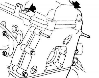
40. Lubricate with elastic sealant, for example, "Drei Bond 1209" or "Loctit Ultra Black" mating surfaces of the timing case cover and cylinder head (arrows in the illustration).
41. Lubricate the transitions to the semicircle of the sealing gasket with the same sealant (arrow on the illustration).
42. Tighten the cylinder head cover with the gasket crosswise to a torque of 10 Nm. Make sure that the gasket does not protrude.
43. Insert and secure the camshaft position sensor with the sealing ring.
44. Secure the exhaust pipe with bolts, refer to Section Removal and installation of the exhaust system.
45. Install the intake manifold, refer to Section Removal and installation the intake manifold.
46. Install the ignition coils, refer to Section Removal and installation ignition coils/ignition cables.
47. Install the spark plugs, refer to Section Spark plugs.

48. Secure the air supply bracket and the electromagnetic valve with the pressure accumulator.
49. Install the thermostat, refer to Section Removal and installation the thermostat.
50. Fill the system with coolant and bleed it, refer to Section Replacing the coolant.
51. Check the engine oil level. If necessary, add oil to the MAX mark.
Since removing the cylinder head is a rather labor-intensive operation and requires a special BMW tool, it is recommended that this work be performed at a service station.
52. Remove the intake manifold, refer to Section Removal and installation the intake manifold.
53. Remove the camshafts, refer to Section Removal and installation camshafts.
54. Remove both intake manifolds from the cylinder head.
55. Tighten the M10 engine mount nuts again to 47 Nm and remove the crane. If M8 nuts are installed, tighten them to 22 Nm.
56. Drain the coolant and disconnect the thermostat housing, refer to Section Removal and installation the thermostat.
57. Unscrew the two mounting bolts and remove the coolant pipe under the intake manifold from the cylinder head.

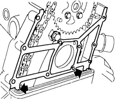
58. Remove the timing gear box cover screws (arrows in the illustration). Note: The camshafts in this and the following illustrations are shown installed, but in reality they must be removed.
59. Loosen the mounting bolts and remove the timing chain guide (arrows in the illustration).
60. Loosen the cylinder head mounting bolts in several steps from the outside in. This operation requires a Torx key, such as the HAZET 2925.
61. Remove any remaining sealant with caulk solvent and a hardwood scraper. Be careful not to let any remaining sealant get into the holes. Cover the holes with rags.
62. Thoroughly clean the threaded holes for the cylinder head bolts from oil and other contaminants using compressed air or a rag wrapped around a narrow screwdriver.
63. Check the guide bushings (arrows in the illustration) for damage and secure fit. They serve to center the cylinder head.
64. Check the flatness of the cylinder head and block with a steel ruler in the longitudinal and transverse directions. If necessary, treat (work of the service station). Maximum deviation from flatness 0.03 mm. The required cylinder head height is given in the Specifications.
65. Lubricate the transitions to the timing case cover with an elastic sealant, for example, "Drei Bond 1209" or "Loctite Ultra Black".
66. Replace the cylinder head gasket. Place the new gasket without sealant so as not to block any holes.
67. Install the cylinder head with the help of an assistant. Do not repaint it, otherwise the new sealing gasket may be damaged.
68. Lubricate the new cylinder head mounting bolts with engine oil. Then tighten the mounting bolts in a spiral pattern evenly from the inside out until they touch.
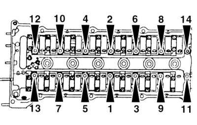
69. Tighten the mounting bolts in sequence 1 through 14 in several steps to the torque values given in the Specifications.

70. Secure the chain guide with bolts.
71. Tighten the timing gear box cover mounting bolts.
72. Secure the coolant pipe to the cylinder head with two bolts, installing new sealing rings
73. Install both exhaust manifolds on the cylinder head, refer to Section Removal and installation the exhaust manifold.
74. Install the camshafts, refer to Section Removal and installation camshafts.
75. Install the intake manifold, refer to Section Removal and installation the intake manifold.
76. Install the thermostat housing, refer to Section Removal and installation the thermostat.
77. Fill the system with coolant, bleed air, refer to Section Replacing the coolant.
78. Check the engine oil level, if necessary, add oil up to the MAX mark.
Signs of a defective cylinder head gasket are listed in Section Removal and installation the intake manifold.
Since removing the cylinder head is a rather labor-intensive operation and requires a special BMW tool, it is recommended to perform it at a service station.
79. Remove the intake manifold, refer to Section Removal and installation the intake manifold.
80. Remove the air cleaner element, refer to Section Replacing the air filter element.
81. Remove the fuel lines and injectors, refer to Section Removal and installation injectors.

82. Unscrew bolts "1" and remove the suction pipe.
83. Disconnect the air mass meter connector by pressing the wire retainer at the plug.
84. Loosen the cylinder head cover mounting bolts crosswise in reverse order, i.e. from 22 to 1.
85. Drain the coolant, including the cylinder block, refer to Section Replacing the coolant.
86. Disconnect the coolant hoses at the thermostat housing by using a screwdriver to lift the wire clips, refer to Section Connecting and disconnecting the quick release coupling.
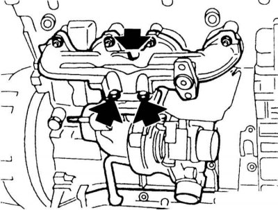
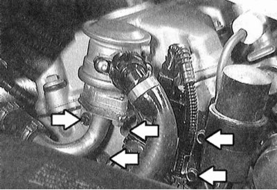
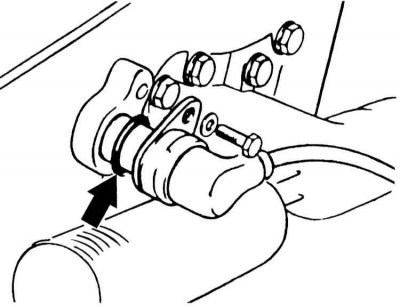
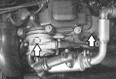
87. Loosen the mounting bolts and remove the turbocharger from the inlet pipe (arrows in the illustration).
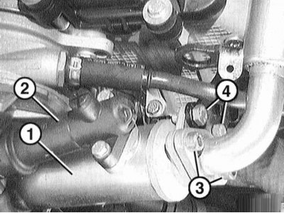
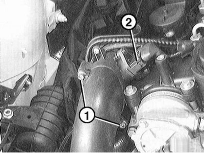
88. Remove the EGR radiator "1" together with the thermostat "2". To do this, release the clamps of both coolant hoses under the EGR radiator and remove the hoses. Unscrew the bolts "3" securing the bracket on both sides of the radiator.
89. Loosen the mounting bolts and remove the coolant pipe under the thermostat housing near the cylinder head. Disconnect the pipe at the cylinder head holder.
90. Remove both camshafts, refer to Section Removal and installation camshafts.
91. Turn out the fingers of the tensioner and shoe in the places marked with arrows.
92. Remove the tensioner shoe upwards.
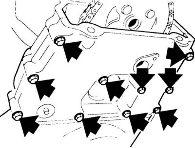
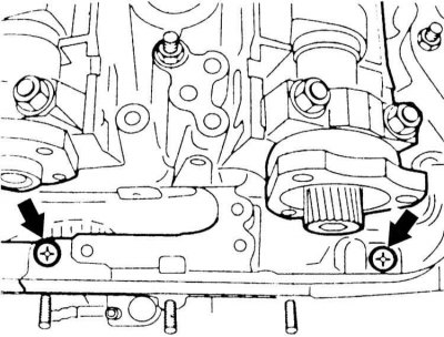
93. Loosen the timing chain box mounting bolts (arrows in the illustration). Also unscrew the bolts invisible in the illustration at points "1" and "2".
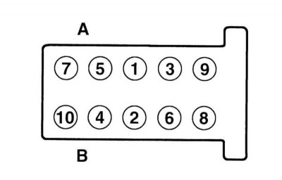
94. Loosen the cylinder head mounting bolts in the reverse order from 10 to 1, unscrewing them by 1/2 turn. Then unscrew them in the same order. A - intake side; B – release side.
95. Remove the cylinder head with the help of an assistant.
96. Lay the new gasket without sealant so as not to block any of the holes. The gasket is marked with a different number of holes depending on its thickness (arrow on the illustration) The new gasket must have the same number of holes as the previous one.

97. The cylinder head mounting bolts are tightened in 5 stages. In each stage, tightening is performed in sequence from bolts 1 to 10. A – intake side, B – exhaust side. Tightening forces are given in the Specifications.
98. Tighten the timing chain box mounting bolts to 15 Nm.
99. Screw in 2 new tension shoe and chain guide pins. The pins are replaceable as their surface has a self-locking coating.
100. Secure the sprocket with the chain on it to the camshaft. Do not tighten the bolts yet.
101. Remove the rod from the chain tensioner so that the chain is taut. Screw the rod plug into the hole in the cylinder head.
102. Install the camshafts, refer to Section Removal and installation camshafts.
103. Secure the coolant hose with a new gasket under the thermostat housing at the cylinder head.
104. Bolt the EGR radiator with new gaskets. Install the coolant hoses and secure them with clamps.
105. Place the coolant hoses on the thermostat housing and secure them, refer to Section Removal and installation the thermostat.
106. Secure the turbocharger with a new seal and new self-locking nuts to the exhaust manifold. Pre-coat the bolts with high-temperature paste. Tighten the nuts to 45 N·m.
107. Be sure to install a new cylinder head cover gasket
108. Seal the corners of the cylinder head cover sealing surface between the cylinder head and the vacuum pump with sealant beads "Drei Bond 1209" or "Loctite Ultra Black" height and width 2 mm.
109. Tighten the cylinder head cover mounting bolts crosswise by hand in sequence from 22 to 1. Then tighten them in the same sequence to a torque of 15 N·m.
110. Connect the air mass meter connector, the plug should lock into place.
111. Secure the inlet manifold with two bolts.
112. Install the injectors and fuel lines, refer to Section Removal and installation injectors.
113. Install the intake manifold, refer to Section Removal and installation the intake manifold.
114. Install the air cleaner element, refer to Section Removal and installation the engine air filter.
The original version is on the portal «bmwman.ru»
Depending on the engine type, year of vehicle manufacture and equipment, electrical wires, vacuum hoses of coolant may have different routing in the engine compartment. Since it is not possible to consider all design options, it is recommended to mark the corresponding wire with tape before disconnecting it.
Signs of a faulty cylinder head gasket include the following:
- Loss of engine power.
- Loss of coolant. White clouds of smoke in the exhaust gases of a warm engine.
- Loss of oil.
- The presence of coolant in the engine oil, the oil level does not decrease, but increases. Gray color of engine oil. Foam bubbles on the level indicator. Dilution of oil.
- Presence of engine oil in the coolant.
- Severe foaming of coolant.
- Poor compression in two adjacent cylinders.
Model 316i, 318i (m43TU engine)
Removal
1. Drain the coolant, including from the cylinder block, refer to Section Replacing the coolant.
2. Remove the thermostat, refer to Section Removal and installation the thermostat.
3. Remove the intake manifold, refer to Section Removal and installation the intake manifold.
4. Remove the spark plugs, refer to Section Spark plugs.
5. Remove the ignition coils, refer to Section Removal and installation ignition coils/ignition cables.
6. Loosen the mounting bolts and remove the exhaust pipe, refer to Section Removal and installation of the exhaust system.
7. Loosen the mounting bolts and remove the cylinder head cover. First, loosen the bolts evenly crosswise, then unscrew them.
8. Loosen the mounting bolts and remove the air supply device holder and the electromagnetic valve with pressure accumulator (arrows in the illustration).
9. Loosen the mounting bolts and remove the camshaft position sensor and take it out together with the sealing ring.
10. Loosen the mounting bolts and remove the upper timing gear box cover. Remove the rubber gasket under the lower cover.
11. Cut from the inside out and remove the cylinder head gasket at the top edge of the lower cover (arrows in the illustration). The gaskets need to be replaced. The gasket for the upper cover of the timing gear box can be used as a spare part.
12. Turn the crankshaft by the central mounting bolt to the right so that the piston of the first cylinder is at TDC. In this case, the arrow on the sprocket points up. You can turn the crankshaft in one of the following ways:
- Apply the parking brake and set the gearbox to neutral. Turn the crankshaft clockwise using the center pulley mounting bolt with a socket wrench.
- Raise the rear of the vehicle and support it on jack stands. Engage fifth gear and release the parking brake. Turn the raised rear wheel. This turns the crankshaft. An assistant is required for this operation.
- Place the car on a level surface. Engage fifth gear. Move the car forward or backward.
13. Fix the camshafts in this position using the BMW-11 3 190 tool shown in the illustration. You can also use the KLANN tool, KL-0580-5.
14. Fix the crankshaft in the TDC position with the BMW-11 2 300 tool or a suitable rod. To do this, insert the rod through the hole in the cylinder block into the hole in the flywheel (arrow on the illustration), after removing the plug.
15. Loosen the camshaft sprocket mounting bolts. Slowly push the tensioner shoe back by the hexagon using a wrench and thus relieve the chain. Remove the sprocket.
16. Loosen the mounting bolts and remove the damper and tension shoe from the cylinder head (arrows in the illustration).
Before loosening the cylinder head mounting bolts, turn the crankshaft back at an angle of 45°. This will prevent the valves from touching the pistons. After installing the cylinder head, turn the crankshaft again to the TDC position of the first cylinder.
17. Loosen the cylinder head mounting bolts from the outside inwards in several steps. A special Torx key, such as HAZET-2925, is required to loosen the bolts.
18. Using an assistant, remove the head from the cylinder block.
If necessary, carefully pry the cylinder head with a screwdriver, being careful not to damage the sealing surface.
Installation
19. Use a scraper to clean the cylinder block sealing surface from any remaining sealing gasket. Make sure that no dirt gets into the cylinder block openings. Cover the openings with rags.
20. Clean the cylinder head sealing surface.
21. Check the flatness of the cylinder head and block with a steel ruler in the longitudinal and transverse directions. If necessary, treat (work of the service station). Maximum deviation from flatness 0.03 mm. The required cylinder head height is given in the Specifications.
22. Thoroughly clean the threaded holes for the cylinder head mounting bolts from oil and other contaminants.
There should be no oil in the threaded holes, otherwise the bolts will not transmit full pressure to the cylinder head, although they are tightened to the specified torque. In addition, this may crack the cylinder block.
23. Check if there are two guide bushings (arrows in the illustration). If not, insert them and check that they are securely seated.
24. Place a new sealing gasket without sealant on the degreased surface of the cylinder block so that the holes remain open.
25. Install the cylinder head with the help of an assistant. At the same time, press back the tensioner shoe with a wrench by the Allen key (arrow on the illustration).
26. Lubricate the new cylinder head mounting bolts with engine oil. Then screw the bolts in and tighten them evenly in a spiral from the inside out until they are snug.
Be sure to install new bolts. Tighten the bolts in several stages. A calibrated torque wrench must be used for tightening.
27. Tighten the cylinder head bolts in sequence 1 through 10 in three steps. Tightening torques are given in Specifications.
The cylinder head bolts must be tightened with particular care. Before tightening, the accuracy of the torque wrench must be checked. In addition, an angle washer, such as HAZET 6690, is required to tighten the bolts. If such a washer is not available, place the wrench, apply a protractor to the wrench lever and mark the 90° angle with chalk. Then turn the wrench in one go until the mark is made.
28. Secure the damper and timing chain tension shoe to the cylinder head.
29. Turn the crankshaft to the TDC position of the first cylinder and insert the rod.
30. Press the tensioner shoe back using the hex key and put on the sprocket with the chain. The arrow on the sprocket should point upwards. Align the oval holes in the center.
31. The camshaft must be fixed at TDC. In this position, secure the sprocket with four bolts to a torque of 10 Nm.
33. Clean the sealing surfaces under the upper timing case cover.
34. Check for damage to the sealing gasket between the upper and lower timing case covers, replace if necessary. Put the gasket down. The raised part of the gasket should fit into the groove on the cylinder head.
35. Replace the timing case cover paper gasket.
36. Apply a thin layer of grease to the top side of the rubber gasket and the BMW-11 2 330 tool. The tool is placed on the sealing gasket before installing the timing case cover. In addition, two BMW-11 4 110 pins are screwed into the upper threaded holes to guide them. A thin steel sheet and two threaded pins can be used instead of the specified tools.
37. Install the timing case cover, insert and screw in the mounting bolts so that the bolt head fits. Remove the BMW-11 2 330 tool.
38. Install the cylinder head cover without the gasket. Screw in the M6 screws with large washers (arrows in the illustration). In this case, the timing case cover should be pressed down so that the upper edges of the case cover and the cylinder head are at the same level. In this position, tighten the timing case cover mounting bolts to a torque of 15 N·m. Remove the guide pins and screw the remaining bolts in their place, tightening them also to a torque of 15 N·m.
39. Remove the cylinder head cover again.
40. Lubricate with elastic sealant, for example, "Drei Bond 1209" or "Loctit Ultra Black" mating surfaces of the timing case cover and cylinder head (arrows in the illustration).
41. Lubricate the transitions to the semicircle of the sealing gasket with the same sealant (arrow on the illustration).
42. Tighten the cylinder head cover with the gasket crosswise to a torque of 10 Nm. Make sure that the gasket does not protrude.
The cylinder head cover is cushioned and sealed by rubber gaskets on the mounting bolts. Therefore, do not turn the rubber gaskets.
43. Insert and secure the camshaft position sensor with the sealing ring.
44. Secure the exhaust pipe with bolts, refer to Section Removal and installation of the exhaust system.
45. Install the intake manifold, refer to Section Removal and installation the intake manifold.
46. Install the ignition coils, refer to Section Removal and installation ignition coils/ignition cables.
47. Install the spark plugs, refer to Section Spark plugs.
48. Secure the air supply bracket and the electromagnetic valve with the pressure accumulator.
49. Install the thermostat, refer to Section Removal and installation the thermostat.
50. Fill the system with coolant and bleed it, refer to Section Replacing the coolant.
51. Check the engine oil level. If necessary, add oil to the MAX mark.
If the cylinder head was removed due to a faulty gasket, change the oil as there may be coolant in the engine oil. Change the oil, refer to Section Changing engine oil and oil filter.
Models 320i, 323i, 328i (m52TU engine)
Removal
Since removing the cylinder head is a rather labor-intensive operation and requires a special BMW tool, it is recommended that this work be performed at a service station.
52. Remove the intake manifold, refer to Section Removal and installation the intake manifold.
53. Remove the camshafts, refer to Section Removal and installation camshafts.
54. Remove both intake manifolds from the cylinder head.
To do this, the engine must be suspended from a crane and one engine support released, refer to Section Removal and installation the oil pan.
55. Tighten the M10 engine mount nuts again to 47 Nm and remove the crane. If M8 nuts are installed, tighten them to 22 Nm.
56. Drain the coolant and disconnect the thermostat housing, refer to Section Removal and installation the thermostat.
57. Unscrew the two mounting bolts and remove the coolant pipe under the intake manifold from the cylinder head.
58. Remove the timing gear box cover screws (arrows in the illustration). Note: The camshafts in this and the following illustrations are shown installed, but in reality they must be removed.
59. Loosen the mounting bolts and remove the timing chain guide (arrows in the illustration).
60. Loosen the cylinder head mounting bolts in several steps from the outside in. This operation requires a Torx key, such as the HAZET 2925.
After removing the cylinder head, do not place it on the sealing surface. This may damage the fully open valves. Place the head on two wooden blocks.
Installation
61. Remove any remaining sealant with caulk solvent and a hardwood scraper. Be careful not to let any remaining sealant get into the holes. Cover the holes with rags.
62. Thoroughly clean the threaded holes for the cylinder head bolts from oil and other contaminants using compressed air or a rag wrapped around a narrow screwdriver.
Do not allow oil to enter the threaded holes, as it will distort the tightening torque of the bolts. In addition, it can cause cracks in the cylinder block.
63. Check the guide bushings (arrows in the illustration) for damage and secure fit. They serve to center the cylinder head.
64. Check the flatness of the cylinder head and block with a steel ruler in the longitudinal and transverse directions. If necessary, treat (work of the service station). Maximum deviation from flatness 0.03 mm. The required cylinder head height is given in the Specifications.
If the cylinder head has been machined, then depending on the height obtained as a result of the machining, it may be necessary to increase the thickness of the sealing gasket by 0.3 mm. This compensates for the reduction in the height of the combustion chamber.
65. Lubricate the transitions to the timing case cover with an elastic sealant, for example, "Drei Bond 1209" or "Loctite Ultra Black".
66. Replace the cylinder head gasket. Place the new gasket without sealant so as not to block any holes.
67. Install the cylinder head with the help of an assistant. Do not repaint it, otherwise the new sealing gasket may be damaged.
68. Lubricate the new cylinder head mounting bolts with engine oil. Then tighten the mounting bolts in a spiral pattern evenly from the inside out until they touch.
Be sure to use new mounting bolts. The bolts must be fastened in three stages. A torque wrench must be used for this operation.
69. Tighten the mounting bolts in sequence 1 through 14 in several steps to the torque values given in the Specifications.
The cylinder head mounting bolts must be tightened with particular care. Before tightening, the accuracy of the torque wrench must be checked. In addition, an angle washer, such as HAZET 6690, is required to tighten the bolts. If such a washer is not available, place the wrench, apply a protractor to the wrench lever and mark the 90° angle with chalk. Then turn the wrench in one go until the mark is made.
70. Secure the chain guide with bolts.
71. Tighten the timing gear box cover mounting bolts.
72. Secure the coolant pipe to the cylinder head with two bolts, installing new sealing rings
73. Install both exhaust manifolds on the cylinder head, refer to Section Removal and installation the exhaust manifold.
74. Install the camshafts, refer to Section Removal and installation camshafts.
75. Install the intake manifold, refer to Section Removal and installation the intake manifold.
76. Install the thermostat housing, refer to Section Removal and installation the thermostat.
77. Fill the system with coolant, bleed air, refer to Section Replacing the coolant.
78. Check the engine oil level, if necessary, add oil up to the MAX mark.
If the cylinder head was removed due to a faulty gasket, change the oil as there may be coolant in the engine oil. For oil changes, refer to Section Changing engine oil and oil filter.
Model 320d (m47 engine)
Removal
Operations and instructions that apply to all engines are given in the Section for engines 316i, 318i. This Section only contains differences that apply to the 320d engine.
Signs of a defective cylinder head gasket are listed in Section Removal and installation the intake manifold.
Since removing the cylinder head is a rather labor-intensive operation and requires a special BMW tool, it is recommended to perform it at a service station.
79. Remove the intake manifold, refer to Section Removal and installation the intake manifold.
80. Remove the air cleaner element, refer to Section Replacing the air filter element.
81. Remove the fuel lines and injectors, refer to Section Removal and installation injectors.
82. Unscrew bolts "1" and remove the suction pipe.
83. Disconnect the air mass meter connector by pressing the wire retainer at the plug.
84. Loosen the cylinder head cover mounting bolts crosswise in reverse order, i.e. from 22 to 1.
85. Drain the coolant, including the cylinder block, refer to Section Replacing the coolant.
86. Disconnect the coolant hoses at the thermostat housing by using a screwdriver to lift the wire clips, refer to Section Connecting and disconnecting the quick release coupling.
87. Loosen the mounting bolts and remove the turbocharger from the inlet pipe (arrows in the illustration).
88. Remove the EGR radiator "1" together with the thermostat "2". To do this, release the clamps of both coolant hoses under the EGR radiator and remove the hoses. Unscrew the bolts "3" securing the bracket on both sides of the radiator.
89. Loosen the mounting bolts and remove the coolant pipe under the thermostat housing near the cylinder head. Disconnect the pipe at the cylinder head holder.
90. Remove both camshafts, refer to Section Removal and installation camshafts.
91. Turn out the fingers of the tensioner and shoe in the places marked with arrows.
92. Remove the tensioner shoe upwards.
93. Loosen the timing chain box mounting bolts (arrows in the illustration). Also unscrew the bolts invisible in the illustration at points "1" and "2".
94. Loosen the cylinder head mounting bolts in the reverse order from 10 to 1, unscrewing them by 1/2 turn. Then unscrew them in the same order. A - intake side; B – release side.
95. Remove the cylinder head with the help of an assistant.
After removal, do not place the cylinder head on the sealing surface, otherwise the glow plugs may be damaged. Place the cylinder head on two wooden blocks.
Installation
96. Lay the new gasket without sealant so as not to block any of the holes. The gasket is marked with a different number of holes depending on its thickness (arrow on the illustration) The new gasket must have the same number of holes as the previous one.
The joints of the timing chain box with the cylinder head are not sealed with sealant. There are additional sealing strips on the gasket in these places (arrows in the illustration).
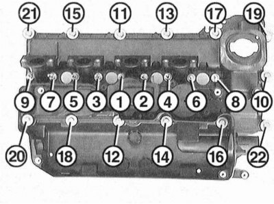
97. The cylinder head mounting bolts are tightened in 5 stages. In each stage, tightening is performed in sequence from bolts 1 to 10. A – intake side, B – exhaust side. Tightening forces are given in the Specifications.
98. Tighten the timing chain box mounting bolts to 15 Nm.
99. Screw in 2 new tension shoe and chain guide pins. The pins are replaceable as their surface has a self-locking coating.
100. Secure the sprocket with the chain on it to the camshaft. Do not tighten the bolts yet.
101. Remove the rod from the chain tensioner so that the chain is taut. Screw the rod plug into the hole in the cylinder head.
102. Install the camshafts, refer to Section Removal and installation camshafts.
103. Secure the coolant hose with a new gasket under the thermostat housing at the cylinder head.
104. Bolt the EGR radiator with new gaskets. Install the coolant hoses and secure them with clamps.
105. Place the coolant hoses on the thermostat housing and secure them, refer to Section Removal and installation the thermostat.
106. Secure the turbocharger with a new seal and new self-locking nuts to the exhaust manifold. Pre-coat the bolts with high-temperature paste. Tighten the nuts to 45 N·m.
107. Be sure to install a new cylinder head cover gasket
108. Seal the corners of the cylinder head cover sealing surface between the cylinder head and the vacuum pump with sealant beads "Drei Bond 1209" or "Loctite Ultra Black" height and width 2 mm.
109. Tighten the cylinder head cover mounting bolts crosswise by hand in sequence from 22 to 1. Then tighten them in the same sequence to a torque of 15 N·m.
110. Connect the air mass meter connector, the plug should lock into place.
111. Secure the inlet manifold with two bolts.
112. Install the injectors and fuel lines, refer to Section Removal and installation injectors.
113. Install the intake manifold, refer to Section Removal and installation the intake manifold.
114. Install the air cleaner element, refer to Section Removal and installation the engine air filter.
The original version is on the portal «bmwman.ru»
This article is available at russian, bulgarian, belarusian, ukrainian, serbian, croatian, romanian, polish, slovak, hungarian
Article verified: Sevastyanov Nikolay
Share information:
Previous articles
БМВ E46: Engine repair
Next articles
Similar articles on other types of BMW cars:
Removal and installation the cylinder head / replacing the cylinder… BMW 5 Series E39 (1995-2003)
Removal and installation of cylinder head — engines M20, M21, M30 BMW 5 Series E34 (1988-1996)
Cylinder head — removal and installation, gasket replacement BMW 7 Series E32 (1986-1994)
Removal and installation cylinder head covers BMW 7 Series E38 (1994-2001)
Removal and installation the cylinder head BMW X3 E83 (2003-2010)
Replacing the cylinder head gasket BMW X5 E53 (1999-2006)
Link in different formats to this page
Visitor comments
No comments yet
- General information
- Manual
- Maintenance
- Power unit
- Engine repair
- Cooling system
- Power system (gasoline)
- Injection system (gasoline)
- Fuel system (diesel)
- Exhaust system
- Ignition system
- Charge and launch systems
- Transmission
- Car gearbox
- Clutch and drive shafts
- Chassis
- Brake system
- Suspension front and rear
- Steering
- Body
- Body care and repair
- Exterior
- Interior
- Electrical equipment
- Troubleshooting
- Lighting and signaling
- Equipment and devices
- Heater and air conditioner
- Electrical circuits
- General information
- Manual
- Repair on the road
- Weekly checks
- Maintenance
- Troubleshooting
- Power unit
- 4 cylinder engines
- 6 cylinder engines
- Engine overhaul
- Cooling and heating
- Fuel and exhaust system
- Starting and charging system
- Ignition system
- Transmission
- Clutch
- Mechanical gearbox
- Automatic gearbox
- Cardan and drive shafts
- Chassis
- Brake system
- Wheel suspension
- Steering
- Body
- Exterior
- Interior
- Electrical equipment
- Equipment and devices
- Electrical circuits
- General information
- Maintenance
- Power unit
- Engine repair
- Cooling system
- Ignition system
- Supply system
- Fuel injection system
- Exhaust system
- Transmission
- Clutch
- Car gearbox
- Front and rear axle
- Chassis
- Steering
- Brake system
- Body
- Exterior
- Interior
- Electrical equipment
- Heating system
- Equipment and devices
- Power devices
- Electrical circuits
- Power unit
- M10/M20 engine
- M40 engine
- Ignition system
- Lubrication system
- Cooling system
- Supply system
- Fuel injection
- Exhaust system
- Transmission
- Clutch
- Manual gearbox
- Front axle
- Rear axle
- Chassis
- Steering
- Brake system
- Body
- Exterior
- Interior
- Electrical equipment
- Heating system
- Equipment and devices
- Electrical circuits
- General information
- Specifications
- Operation and maintenance
- 4-cylinder engine
- Engine repair
- Cooling and lubrication system
- Supply system
- Ignition system
- 6-cylinder engine
- Engine repair
- Cooling and lubrication system
- Supply system
- Fuel injection system
- Ignition system
- Transmission
- Clutch
- 4-speed manual gearbox
- 5-speed manual gearbox
- Automatic gearbox
- Cardan and rear axle
- Chassis
- Steering
- Front suspension
- Rear suspension
- Brake system
- Electrical equipment
- Equipment and devices
- Electrical circuits