
Table of contents: Models 320i, 323i, 328i (engine…↓ Model 320d (m47 engine) ↓
- Home
- BMW 3 Series
- E46
- Power unit
- Engine repair
- Removal and installation camshafts
Removal and installation camshafts (BMW 3 Series E46)
The camshafts of a 4-valve engine can be removed if, for example, it is necessary to loosen the cylinder head mounting bolts. Since this requires a special BMW tool, it is recommended that this operation be carried out at a BMW service station.
All valve train components, such as bearing shells or disc springs and toothed bushings on sprockets, must be installed in their original locations. To do this, they must be placed on a special tray.
1. Remove the air filter housing, refer to Section Removal and installation the engine air filter.
2. Remove the spark plugs, refer to Section Spark plugs.
3. Disconnect the crankcase ventilation pipe at the cylinder head cover of the pipeline.

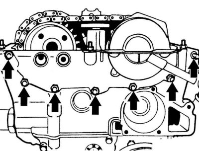
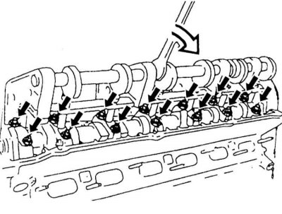
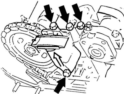
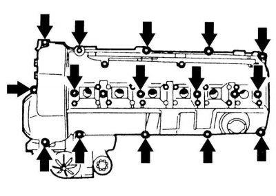
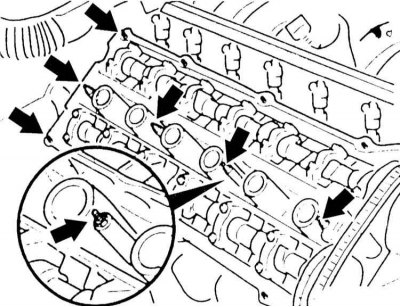
4. Loosen the mounting bolts and remove the cylinder head cover (arrows in the illustration). At the same time, pay attention to the rubber gaskets of the mounting bolts so that you can install them correctly later.
5. Remove the fan/fan clutch, refer to Section Removal and installation a fan with a viscous coupling.
6. Remove the intake camshaft cover.

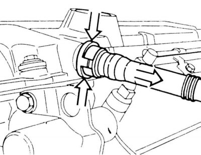
7. Disconnect the oil line (arrow on the illustration) for a double VANOS block.
8. Instead of the oil line, connect compressed air to the double VANOS block via a suitable adapter and supply air at a pressure of 2 to 8 bar.
9. Turn the crankshaft at least two revolutions clockwise with the VANOS unit under load. You can turn the crankshaft and, accordingly, the engine in one of the following ways:
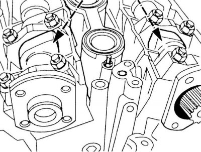
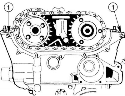
10. Set the crankshaft to the TDC position of the first cylinder. The tops of the cams (arrows in the illustration) intake and exhaust valves of the first cylinder (from the timing drive side) must be facing upward.

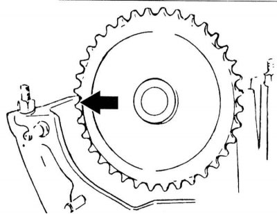
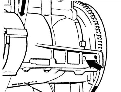
11. Lock the crankshaft in the TDC position using the BMW tool or another suitable rod. To do this, insert the rod into the hole in the cylinder block (arrow on the illustration) into the flywheel hole, having first removed the plug in the cylinder block.

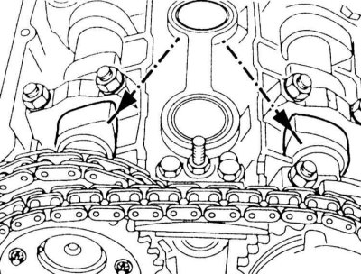
12. Unscrew the studs (arrows in the illustration).

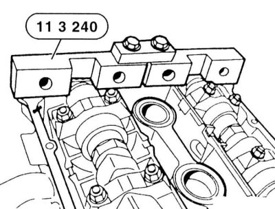
13. Fix the camshafts with the BMW-11 3 240 tool shown in the illustration in the TDC position of the first cylinder. You can use the KLANI KL-0580-4 tool. The tool is installed through the hexagon of the camshafts and placed on the edge of the cylinder head.
14. Disconnect the compressed air from the VANOS unit "4".
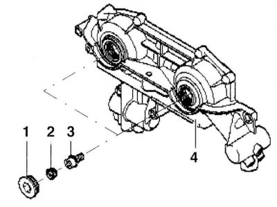
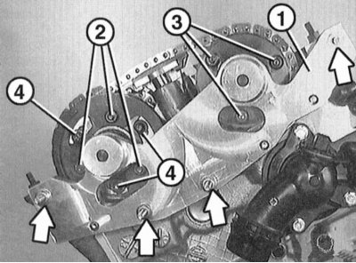
15. Unscrew the threaded plugs "1" in the axes of the intake and exhaust valve camshafts, wipe off the leaked oil.
16. Use pliers to remove the caps "2" under the plugs.
17. Unscrew the calibrated bolts "3" under the covers.
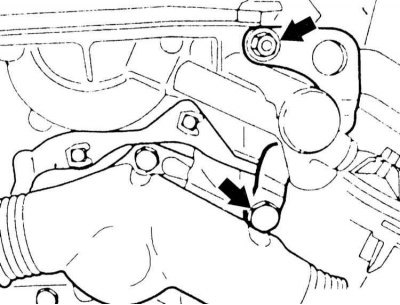
18. Unscrew the eye (arrows in the illustration).
19. Disconnect the connector at the VANOS unit.
20. Unscrew the nuts (arrows in the illustration) and remove the VANOS unit.

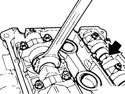
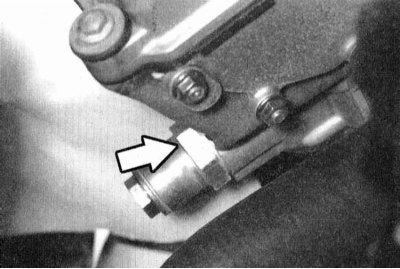
21. Unscrew the chain tensioner (arrow on the illustration) at the cylinder head.
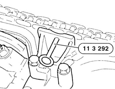
22. Press the upper chain tensioner against the connecting chain between the camshafts and secure it in this position by inserting the BMW-11 3 292 tool.
23. Unscrew the three nuts securing the sensor to the exhaust camshaft sprocket. Remove the sensor wheel from the disc spring from the sprocket.
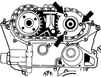
24. Unscrew the mounting nuts (arrows in the illustration) on the intake camshaft sprocket. Remove the thrust washer from the sprocket.
25. Unscrew the three bolts securing the exhaust camshaft sprocket.
26. Remove both sprockets with the chain from the camshafts.

27. Disconnect the upper chain tensioner (arrows in the illustration).
28. Disconnect the sprocket from the camshaft.
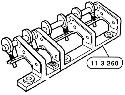
29. To remove the camshafts, you need the BMW 11 3 260 tool. It is designed for all camshaft bearings in the installation position, when the bearing shells are released. The removal procedure for both camshafts is the same, the sequence of removal is not important.
30. Remove the spark plugs. Install the tool and tighten it in the threaded holes of the spark plugs of cylinders 1 and 4 to a torque of 25 N·m.
31. Turn the eccentric shaft in the direction of the arrow with a wrench and secure the bearing caps.
32. Loosen the mounting bolts of all bearing caps.
33. Loosen the device and remove it.
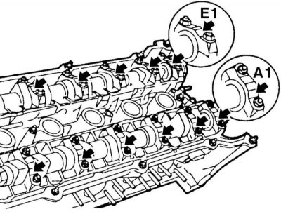
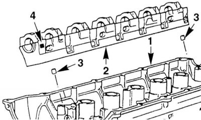
34. Remove the bearing caps and camshafts. Place the caps in the order they were installed on the engine. The same order must be followed when installing the caps on the engine. The bearing caps of the exhaust camshaft are marked A1 through A7, and the inlet camshafts are marked E1 through E7 (arrows in the illustration).

35. If necessary, for example to remove the valves, remove the bearing strip "2" with the tappets as a set. Pay attention to the centering bushings "2". The bearing strips at point "2" are marked "A" for the exhaust side and "E" for the intake side.
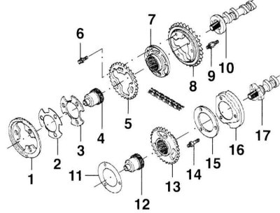
VANOS unit drive chain sprockets
1 - pulse sensor wheel
2 - disc spring
3 - thrust washer 3.5 mm
4 - toothed shaft
5 - star
6 — TORX screw
7 - toothed sleeve
8 - asterisk
9 — pin
10 — intake camshaft
11 - figured washer
12 — toothed shaft
13 - asterisk
14 — pin
15 - thrust washer
16 — pulse sensor wheel
17 — intake camshaft
1. Check the surface of the tappets, replace them if there are any defects. Install the camshafts so that the tops of the cams of the first cylinder point towards each other.
2. Install the bar with bearings and inserted pushers into the cylinder head. Check for the presence of centering bushings "3".
3. Insert the bearing shells according to the marking. They must be located in their original places.
4. Insert the tool and clamp the liners.
5. Tighten the camshaft bearing shells to 15 Nm.
6. Remove the device.

7. Insert a ruler to fix the camshafts.
8. If necessary. Arrow - hexagon of the second camshaft.
9. Secure the sensor wheel and thrust washer to the intake camshaft with a torque of 20 Nm.
10. Install the sprocket on the exhaust camshaft. The arrow on the sprocket should point toward the top edge of the cylinder head.
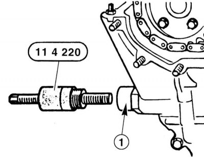
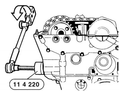
11. The chain tensioner piston "1" is unscrewed. Screw the BMW tool – 11 4 220 into the tensioner thread.
12. Lightly tighten the chain tensioner by turning the tension screw of the BMW tool – 11 4 220. The chain must not sag.

13. Align the sprocket on the exhaust camshaft. The arrow on the sprocket should point toward the top edge of the cylinder head.
14. Secure the sprocket to the exhaust camshaft with three bolts to a torque of 28 Nm.
15. Secure the upper chain tensioner.
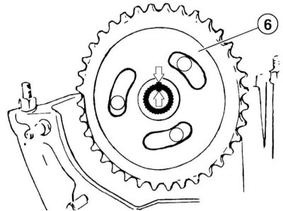
16. Insert the toothed sleeve "6". The toothed grooves on the camshaft and the toothed sleeve should be opposite each other (arrows in the illustration).
17. Insert the toothed shaft so that the sprocket mounting bolts lie in the center of the oval holes in the toothed sleeve.
18. Place the upper chain on the sprockets and align it according to the markings made when removing it. If new parts are being installed, transfer the markings from the old parts to them.

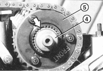
19. Place the upper chain with both sprockets on the camshafts. In this case, the tooth grooves (arrow on the illustration) on the intake camshaft and on the sprocket should be opposite each other. Insert the toothed shaft "4" with pins into the tooth cavities and press.
20. Again, pull out the toothed shaft "4" a little so that 1 mm of tooth width is visible.
21. Install the thrust washer on the intake camshaft sprocket so that the "FRONT" marking can be read. Tighten the sprocket mounting nuts until they stick, but do not tighten them.
22. Secure the camshaft sprocket by tightening the nuts to 5 Nm, then loosen them again by half a turn.
23. Install the thrust washer on the intake camshaft sprocket so that the "F" lettering is visible. If the lettering is not visible, pay attention to the installation direction of the thrust washer: The large adjacent diameter should point toward the camshaft.
24. Install the sensor wheel on the exhaust camshaft sprocket. The arrow on the wheel should point outward toward the top edge of the cylinder head.
25. Pull out the toothed shaft on the exhaust camshaft sprocket until it stops.

26. Press the upper chain tensioner with your hand and remove the BMW locking tool.
27. Tighten the chain by turning the tension screw of the BMW-11 4 220 tool to a torque of 0.7 Nm.
28. Clean the sealing surface of the VANOS unit from oil and dirt. Check the presence of guide bushings "1".
29. Fasten the tool BMW-11 6 150 "1" (arrows in the illustration). This tool is used to secure the toothed bushings when tensioning the sprockets.
30. Tighten the three nuts "2" and "3" to both sprockets first with a torque of 5 Nm, without tightening them.
31. Tighten bolts "4" in the grooves to a torque of 22 Nm.
32. Tighten nuts "2" and "3" to 22 Nm.
33. Disconnect with tool BMW-11 6 150.
34. Seal the corners of the sealing surface between the cylinder head and the VANOS block with sealant "Drei Bond 1209" or "Loctite Ultra Black".

35. Replace the VANOS unit sealing gasket. Secure the unit (arrows in the illustration). Tighten the M6 nuts to 10 Nm and the M6 nuts to 22 Nm.
36. Connect the connector at the VANOS unit.
37. Install the guide bolts on the intake and exhaust camshafts and tighten to 10 Nm.
38. Replace the caps located under the screw plugs and insert them with pliers.
39. Tighten the threaded plugs with new sealing rings at the inlet and outlet camshafts and tighten to a torque of 50 N·m.
40. Secure the engine lug at the front with bolts.
41. Remove the special tool for fixing the camshaft and crankshaft.
42. Connect the compressed air line using an adapter and supply air with a pressure of 2 – 8 bar.
43. Turn the crankshaft at least two turns clockwise with the VANOS unit under air pressure.
44. Set the engine to the TDC position of the first cylinder. The tops of the cams of the intake and exhaust valves of the first cylinder (arrows in the illustration) must be facing upward at the same time.
45. Reinsert the crankshaft locking rod.
46. Reinsert the camshaft locking rod.
47. Remove the camshaft alignment ruler.
48. Remove the compressed air connection from the VANOS unit. Secure the oil line to the VANOS unit with new seals to a torque of 30 Nm. Connect the connector.

49. Unscrew the BMW-11 4 220 tool at the chain tensioner.
50. Unscrew the chain tension piston with a new sealing ring to a torque of 70 Nm.
51. Screw in the cylinder head cover pin.
52. Install the intake camshaft cover.
53. Lubricate the mating surfaces between the VANOS block and the cylinder head with sealant, e.g, "Drei Bond 1209" or "Loctite Ultra Black".
54. Using the same sealant, lubricate the transitions to the semicircles of the sealing surface to the cylinder head cover.
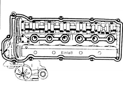
55. Install the cylinder head covers. Replace damaged gaskets, refer to the accompanying illustration. When installing the cylinder head cover gasket, pay particular attention to the correct position in the semicircles of the end face of the cylinder head. Tighten the cover evenly with a torque of 10 N·m.
56. Insert the cylinder recognition sensor and secure it. If the sealing ring is damaged, replace it.
57. Install the spark plugs, refer to Section Spark plugs.
58. Install the exhaust manifold and downpipe, refer to Section Removal and installation the exhaust manifold.

59. Install the crankcase ventilation connection on the cylinder head cover and secure it.
60. Install the fan/fan clutch, refer to Section Removal and installation a fan with a viscous coupling.
61. Install the air cleaner housing, refer to Section Removal and installation the engine air filter.
1. Remove the vacuum pump, refer to the relevant section.
2. Remove the cylinder head cover, refer to Section Removal and installation the cylinder head/replacing the sealing gasket.
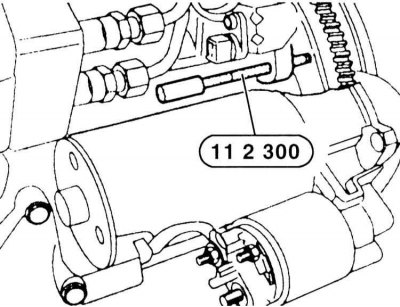
3. Fix the crankshaft in the TDC position with the BMW-11 2 300 tool or another suitable rod. To do this, insert the rod through the hole in the cylinder block above the starter into the hole in the flywheel.
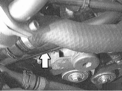
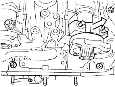
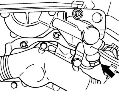
4. Fix the chain tensioner in the compressed position. To do this, unscrew the Allen screw in the area of the end wall of the cylinder block (arrow on the illustration) and insert the BMW -11 3 340 rod or other suitable rod.
5. Loosen the mounting bolts and remove the upper chain guide.
6. Loosen the mounting bolts and remove both camshaft sprockets. Hold the shafts by the hexagon. To secure the intake camshaft, the BMW service station uses the BMW -11 6 320 tool.
7. Loosen the mounting bolts and remove the camshaft bearing caps. Place them in the order of installation. Remove the camshafts.
8. Remove the rocker arms from the cylinder head and place them on the engine in the order of installation. Tightening torques are given in Specifications.
The original article is available on the website: BMWMan.ru
When installing without a special tool, there is a risk of damaging the camshafts. In addition, the valves can be bent when in contact with the piston crowns.
All valve train components, such as bearing shells or disc springs and toothed bushings on sprockets, must be installed in their original locations. To do this, they must be placed on a special tray.
Models 320i, 323i, 328i (engine M52TU)
Removal
1. Remove the air filter housing, refer to Section Removal and installation the engine air filter.
2. Remove the spark plugs, refer to Section Spark plugs.
3. Disconnect the crankcase ventilation pipe at the cylinder head cover of the pipeline.
4. Loosen the mounting bolts and remove the cylinder head cover (arrows in the illustration). At the same time, pay attention to the rubber gaskets of the mounting bolts so that you can install them correctly later.
5. Remove the fan/fan clutch, refer to Section Removal and installation a fan with a viscous coupling.
6. Remove the intake camshaft cover.
7. Disconnect the oil line (arrow on the illustration) for a double VANOS block.
8. Instead of the oil line, connect compressed air to the double VANOS block via a suitable adapter and supply air at a pressure of 2 to 8 bar.
This and the following operations are necessary to set the camshafts to their basic position.
9. Turn the crankshaft at least two revolutions clockwise with the VANOS unit under load. You can turn the crankshaft and, accordingly, the engine in one of the following ways:
- Shift the gearbox into neutral and apply the parking brake. Turn the crankshaft clockwise using the central pulley mounting bolt using the socket.
- Raise and support the vehicle on the rear side. Engage fifth gear and release the parking brake. Turn the raised rear wheel forward. This will simultaneously turn the crankshaft
- Place the car on a level surface. Engage fifth gear. Carefully move or ask to move the car forward.
10. Set the crankshaft to the TDC position of the first cylinder. The tops of the cams (arrows in the illustration) intake and exhaust valves of the first cylinder (from the timing drive side) must be facing upward.
11. Lock the crankshaft in the TDC position using the BMW tool or another suitable rod. To do this, insert the rod into the hole in the cylinder block (arrow on the illustration) into the flywheel hole, having first removed the plug in the cylinder block.
12. Unscrew the studs (arrows in the illustration).
13. Fix the camshafts with the BMW-11 3 240 tool shown in the illustration in the TDC position of the first cylinder. You can use the KLANI KL-0580-4 tool. The tool is installed through the hexagon of the camshafts and placed on the edge of the cylinder head.
14. Disconnect the compressed air from the VANOS unit "4".
After opening the threaded plugs, oil flows out. Prepare a rag and a container. Immediately wipe off any oil that gets on the rubber elements and V-belt.
15. Unscrew the threaded plugs "1" in the axes of the intake and exhaust valve camshafts, wipe off the leaked oil.
16. Use pliers to remove the caps "2" under the plugs.
17. Unscrew the calibrated bolts "3" under the covers.
18. Unscrew the eye (arrows in the illustration).
19. Disconnect the connector at the VANOS unit.
20. Unscrew the nuts (arrows in the illustration) and remove the VANOS unit.
After removing the VANOS unit, do not turn the engine. The toothed shaft of the intake camshaft may slip out of the splined connection and the valves will become uncontrollable and may hit the piston crown.
21. Unscrew the chain tensioner (arrow on the illustration) at the cylinder head.
22. Press the upper chain tensioner against the connecting chain between the camshafts and secure it in this position by inserting the BMW-11 3 292 tool.
23. Unscrew the three nuts securing the sensor to the exhaust camshaft sprocket. Remove the sensor wheel from the disc spring from the sprocket.
24. Unscrew the mounting nuts (arrows in the illustration) on the intake camshaft sprocket. Remove the thrust washer from the sprocket.
Before unscrewing the nuts securing the exhaust camshaft sprocket, trace the nuts with a felt-tip pen so that the sprocket can be secured in its original position during installation. Otherwise, the sprockets can only be correctly aligned using a special BMW tool.
25. Unscrew the three bolts securing the exhaust camshaft sprocket.
26. Remove both sprockets with the chain from the camshafts.
27. Disconnect the upper chain tensioner (arrows in the illustration).
28. Disconnect the sprocket from the camshaft.
29. To remove the camshafts, you need the BMW 11 3 260 tool. It is designed for all camshaft bearings in the installation position, when the bearing shells are released. The removal procedure for both camshafts is the same, the sequence of removal is not important.
30. Remove the spark plugs. Install the tool and tighten it in the threaded holes of the spark plugs of cylinders 1 and 4 to a torque of 25 N·m.
31. Turn the eccentric shaft in the direction of the arrow with a wrench and secure the bearing caps.
32. Loosen the mounting bolts of all bearing caps.
The cover of the first bearing of the intake camshaft is centered by bushings. To prevent the camshaft from being skewed, unscrew the bolts securing the cover of the first bearing and remove it.
33. Loosen the device and remove it.
34. Remove the bearing caps and camshafts. Place the caps in the order they were installed on the engine. The same order must be followed when installing the caps on the engine. The bearing caps of the exhaust camshaft are marked A1 through A7, and the inlet camshafts are marked E1 through E7 (arrows in the illustration).
35. If necessary, for example to remove the valves, remove the bearing strip "2" with the tappets as a set. Pay attention to the centering bushings "2". The bearing strips at point "2" are marked "A" for the exhaust side and "E" for the intake side.
The valve tappets can slip down from the bearing plate if they are not secured. BMW service stations use suction cups for this purpose, which can be installed on top of the tappet and prevent slipping. Mark the tappets. They must be installed in their original place if they were removed from the plate. 1 - cylinder head.
Do not place the removed tappets on the head for more than 10 minutes, otherwise the engine oil will leak out and the automatic valve clearance compensation will stop working.
VANOS unit drive chain sprockets
1 - pulse sensor wheel
2 - disc spring
3 - thrust washer 3.5 mm
4 - toothed shaft
5 - star
6 — TORX screw
7 - toothed sleeve
8 - asterisk
9 — pin
10 — intake camshaft
11 - figured washer
12 — toothed shaft
13 - asterisk
14 — pin
15 - thrust washer
16 — pulse sensor wheel
17 — intake camshaft
Installation
Before installing the camshafts, turn the crankshaft approximately 30° against the direction of engine rotation (to the left by the pulley hexagon) through TDC. This way, none of the pistons will be at the top and the valves can be put back in place. The hydraulic valve lifters are pulled out without a load from the camshaft and after installation, they take some time to compress again. As a result, the valves can be opened more than corresponds to the position of the camshaft and can sit on the pistons. Therefore, after installing the camshafts, you must wait 40 minutes until you can turn the engine. Only then can you turn the crankshaft to the TDC position and install the timing chains, refer to the subsection Installing the cylinder head.
1. Check the surface of the tappets, replace them if there are any defects. Install the camshafts so that the tops of the cams of the first cylinder point towards each other.
2. Install the bar with bearings and inserted pushers into the cylinder head. Check for the presence of centering bushings "3".
3. Insert the bearing shells according to the marking. They must be located in their original places.
4. Insert the tool and clamp the liners.
5. Tighten the camshaft bearing shells to 15 Nm.
6. Remove the device.
7. Insert a ruler to fix the camshafts.
8. If necessary. Arrow - hexagon of the second camshaft.
Be careful not to damage the camshaft housing. If necessary, grind the outside of the wrench.
9. Secure the sensor wheel and thrust washer to the intake camshaft with a torque of 20 Nm.
10. Install the sprocket on the exhaust camshaft. The arrow on the sprocket should point toward the top edge of the cylinder head.
11. The chain tensioner piston "1" is unscrewed. Screw the BMW tool – 11 4 220 into the tensioner thread.
The specified tool presses on the chain and slightly tightens it so that the camshaft sprockets are in their working position. With some skills, such a tool can be made independently. Without the tool, proper installation of the chain is impossible.
12. Lightly tighten the chain tensioner by turning the tension screw of the BMW tool – 11 4 220. The chain must not sag.
13. Align the sprocket on the exhaust camshaft. The arrow on the sprocket should point toward the top edge of the cylinder head.
14. Secure the sprocket to the exhaust camshaft with three bolts to a torque of 28 Nm.
15. Secure the upper chain tensioner.
16. Insert the toothed sleeve "6". The toothed grooves on the camshaft and the toothed sleeve should be opposite each other (arrows in the illustration).
17. Insert the toothed shaft so that the sprocket mounting bolts lie in the center of the oval holes in the toothed sleeve.
18. Place the upper chain on the sprockets and align it according to the markings made when removing it. If new parts are being installed, transfer the markings from the old parts to them.
19. Place the upper chain with both sprockets on the camshafts. In this case, the tooth grooves (arrow on the illustration) on the intake camshaft and on the sprocket should be opposite each other. Insert the toothed shaft "4" with pins into the tooth cavities and press.
20. Again, pull out the toothed shaft "4" a little so that 1 mm of tooth width is visible.
21. Install the thrust washer on the intake camshaft sprocket so that the "FRONT" marking can be read. Tighten the sprocket mounting nuts until they stick, but do not tighten them.
22. Secure the camshaft sprocket by tightening the nuts to 5 Nm, then loosen them again by half a turn.
23. Install the thrust washer on the intake camshaft sprocket so that the "F" lettering is visible. If the lettering is not visible, pay attention to the installation direction of the thrust washer: The large adjacent diameter should point toward the camshaft.
24. Install the sensor wheel on the exhaust camshaft sprocket. The arrow on the wheel should point outward toward the top edge of the cylinder head.
25. Pull out the toothed shaft on the exhaust camshaft sprocket until it stops.
26. Press the upper chain tensioner with your hand and remove the BMW locking tool.
27. Tighten the chain by turning the tension screw of the BMW-11 4 220 tool to a torque of 0.7 Nm.
28. Clean the sealing surface of the VANOS unit from oil and dirt. Check the presence of guide bushings "1".
29. Fasten the tool BMW-11 6 150 "1" (arrows in the illustration). This tool is used to secure the toothed bushings when tensioning the sprockets.
30. Tighten the three nuts "2" and "3" to both sprockets first with a torque of 5 Nm, without tightening them.
31. Tighten bolts "4" in the grooves to a torque of 22 Nm.
32. Tighten nuts "2" and "3" to 22 Nm.
33. Disconnect with tool BMW-11 6 150.
34. Seal the corners of the sealing surface between the cylinder head and the VANOS block with sealant "Drei Bond 1209" or "Loctite Ultra Black".
35. Replace the VANOS unit sealing gasket. Secure the unit (arrows in the illustration). Tighten the M6 nuts to 10 Nm and the M6 nuts to 22 Nm.
36. Connect the connector at the VANOS unit.
37. Install the guide bolts on the intake and exhaust camshafts and tighten to 10 Nm.
38. Replace the caps located under the screw plugs and insert them with pliers.
39. Tighten the threaded plugs with new sealing rings at the inlet and outlet camshafts and tighten to a torque of 50 N·m.
40. Secure the engine lug at the front with bolts.
41. Remove the special tool for fixing the camshaft and crankshaft.
42. Connect the compressed air line using an adapter and supply air with a pressure of 2 – 8 bar.
43. Turn the crankshaft at least two turns clockwise with the VANOS unit under air pressure.
44. Set the engine to the TDC position of the first cylinder. The tops of the cams of the intake and exhaust valves of the first cylinder (arrows in the illustration) must be facing upward at the same time.
45. Reinsert the crankshaft locking rod.
46. Reinsert the camshaft locking rod.
The ruler for fixing the camshafts may rise 1 mm above the intake camshaft. If the ruler on the exhaust manifold side is high, it is necessary to adjust the valve timing by turning the camshaft sprockets. To do this, loosen the sprockets on the camshafts, turn them and then tighten them again with a torque of 22 N·m.
47. Remove the camshaft alignment ruler.
48. Remove the compressed air connection from the VANOS unit. Secure the oil line to the VANOS unit with new seals to a torque of 30 Nm. Connect the connector.
49. Unscrew the BMW-11 4 220 tool at the chain tensioner.
50. Unscrew the chain tension piston with a new sealing ring to a torque of 70 Nm.
51. Screw in the cylinder head cover pin.
52. Install the intake camshaft cover.
53. Lubricate the mating surfaces between the VANOS block and the cylinder head with sealant, e.g, "Drei Bond 1209" or "Loctite Ultra Black".
54. Using the same sealant, lubricate the transitions to the semicircles of the sealing surface to the cylinder head cover.
55. Install the cylinder head covers. Replace damaged gaskets, refer to the accompanying illustration. When installing the cylinder head cover gasket, pay particular attention to the correct position in the semicircles of the end face of the cylinder head. Tighten the cover evenly with a torque of 10 N·m.
56. Insert the cylinder recognition sensor and secure it. If the sealing ring is damaged, replace it.
57. Install the spark plugs, refer to Section Spark plugs.
58. Install the exhaust manifold and downpipe, refer to Section Removal and installation the exhaust manifold.
Before starting the engine, remove the TDC position rod from the flywheel. Reinstall the plug in the hole on the cylinder block.
59. Install the crankcase ventilation connection on the cylinder head cover and secure it.
60. Install the fan/fan clutch, refer to Section Removal and installation a fan with a viscous coupling.
61. Install the air cleaner housing, refer to Section Removal and installation the engine air filter.
Model 320d (m47 engine)
Removal
Operations and instructions that apply to all engines are given in the Section for engines 316i, 318i. This Section only contains differences that apply to the 320d engine.
1. Remove the vacuum pump, refer to the relevant section.
2. Remove the cylinder head cover, refer to Section Removal and installation the cylinder head/replacing the sealing gasket.
3. Fix the crankshaft in the TDC position with the BMW-11 2 300 tool or another suitable rod. To do this, insert the rod through the hole in the cylinder block above the starter into the hole in the flywheel.
4. Fix the chain tensioner in the compressed position. To do this, unscrew the Allen screw in the area of the end wall of the cylinder block (arrow on the illustration) and insert the BMW -11 3 340 rod or other suitable rod.
5. Loosen the mounting bolts and remove the upper chain guide.
6. Loosen the mounting bolts and remove both camshaft sprockets. Hold the shafts by the hexagon. To secure the intake camshaft, the BMW service station uses the BMW -11 6 320 tool.
7. Loosen the mounting bolts and remove the camshaft bearing caps. Place them in the order of installation. Remove the camshafts.
8. Remove the rocker arms from the cylinder head and place them on the engine in the order of installation. Tightening torques are given in Specifications.
The original article is available on the website: BMWMan.ru
This article is available at russian, bulgarian, belarusian, ukrainian, serbian, croatian, romanian, polish, slovak, hungarian
Article verified: Sevastyanov Nikolay
Share information:
Previous articles
БМВ E46: Engine repair
Next articles
Similar articles on other types of BMW cars:
Removal and installation the oil pan BMW 5 Series E12 (1972-1981)
Removal and installation of cylinder heads, camshafts and their… BMW 7 Series E38 (1994-2001)
Cylinder Head Cover — Removal and Installation BMW 7 Series E32 (1986-1994)
Pistons — removal and installation BMW X3 E83 (2003-2010)
Removal and installation the engine BMW X5 E53 (1999-2006)
Link in different formats to this page
Visitor comments
No comments yet
- General information
- Manual
- Maintenance
- Power unit
- Engine repair
- Cooling system
- Power system (gasoline)
- Injection system (gasoline)
- Fuel system (diesel)
- Exhaust system
- Ignition system
- Charge and launch systems
- Transmission
- Car gearbox
- Clutch and drive shafts
- Chassis
- Brake system
- Suspension front and rear
- Steering
- Body
- Body care and repair
- Exterior
- Interior
- Electrical equipment
- Troubleshooting
- Lighting and signaling
- Equipment and devices
- Heater and air conditioner
- Electrical circuits
- General information
- Manual
- Repair on the road
- Weekly checks
- Maintenance
- Troubleshooting
- Power unit
- 4 cylinder engines
- 6 cylinder engines
- Engine overhaul
- Cooling and heating
- Fuel and exhaust system
- Starting and charging system
- Ignition system
- Transmission
- Clutch
- Mechanical gearbox
- Automatic gearbox
- Cardan and drive shafts
- Chassis
- Brake system
- Wheel suspension
- Steering
- Body
- Exterior
- Interior
- Electrical equipment
- Equipment and devices
- Electrical circuits
- General information
- Maintenance
- Power unit
- Engine repair
- Cooling system
- Ignition system
- Supply system
- Fuel injection system
- Exhaust system
- Transmission
- Clutch
- Car gearbox
- Front and rear axle
- Chassis
- Steering
- Brake system
- Body
- Exterior
- Interior
- Electrical equipment
- Heating system
- Equipment and devices
- Power devices
- Electrical circuits
- Power unit
- M10/M20 engine
- M40 engine
- Ignition system
- Lubrication system
- Cooling system
- Supply system
- Fuel injection
- Exhaust system
- Transmission
- Clutch
- Manual gearbox
- Front axle
- Rear axle
- Chassis
- Steering
- Brake system
- Body
- Exterior
- Interior
- Electrical equipment
- Heating system
- Equipment and devices
- Electrical circuits
- General information
- Specifications
- Operation and maintenance
- 4-cylinder engine
- Engine repair
- Cooling and lubrication system
- Supply system
- Ignition system
- 6-cylinder engine
- Engine repair
- Cooling and lubrication system
- Supply system
- Fuel injection system
- Ignition system
- Transmission
- Clutch
- 4-speed manual gearbox
- 5-speed manual gearbox
- Automatic gearbox
- Cardan and rear axle
- Chassis
- Steering
- Front suspension
- Rear suspension
- Brake system
- Electrical equipment
- Equipment and devices
- Electrical circuits