
Removal
1. Disconnect the negative cable from the battery. Remove the cylinder head cover.
2. Remove the drive belts (see section Replacing drive belts and their tensioners).
3. Drain the engine cooling system.
4. Remove the vacuum pump (see section Removal and installation a vacuum pump).
5. Remove the lower engine guards and loosen the turbocharger bracket bolts.
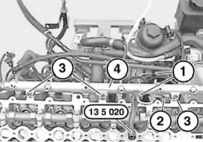
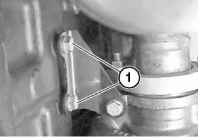
6. Using special tool No.13 5 020, remove the high pressure pipe (1).
When installing, ensure that the rubber cushion (2) is in the correct position. Unscrew the bolts (3) and remove the fuel distribution line (4).
7. Disconnect the turbocharger from the exhaust manifold.
A new turbocharger gasket will be required during installation; lubricate the threads with copper-containing grease.
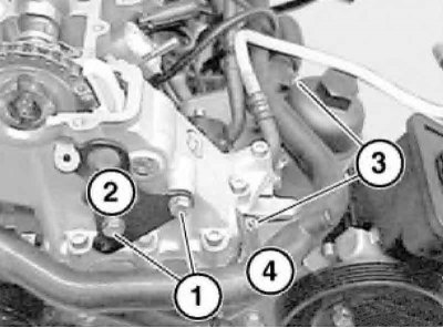
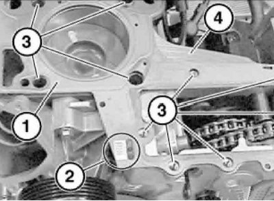
8. Unscrew screws 1 and 3 and remove eye 2 and return pipe 4.
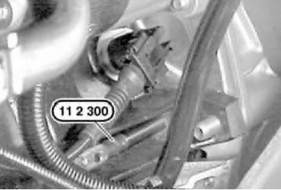
9. Remove the plug from the rear of the crankcase, below the starter, and turn the engine clockwise using tool No.11 6 480 at the front of the vibration damper. Fix the engine in the position of the piston of the first cylinder at TDC at the end of the compression stroke by inserting tool No.11 2 300 into the hole opened under the plug.
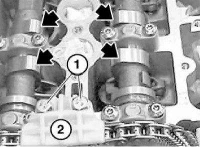
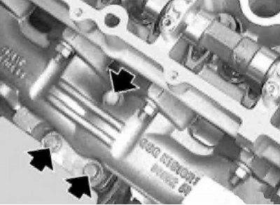
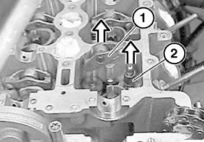
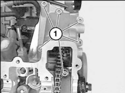
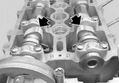
10. In the TDC position, the tops of the camshaft cams that control the valves of the first cylinder should be directed towards each other (arrows). Unscrew the screws (1) and remove the timing chain guide (2).
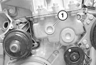
11. Unscrew the threaded plug.
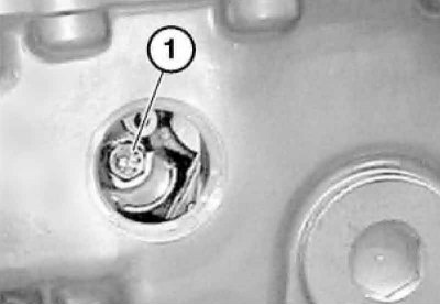
12. Release the pressure by loosening the chain tensioner bolt.
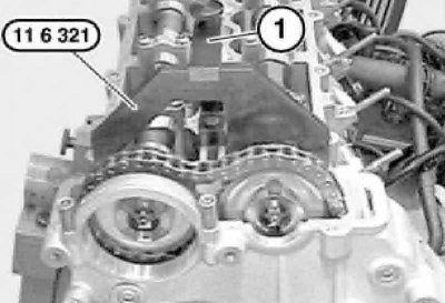
13. Install attachment No.11 6 322 (1) on the cylinder head, place attachment No.11 6 321 on the camshaft of the intake valves and secure with attachment No.11 6 322.
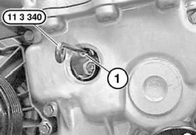
14. Slowly turn the exhaust camshaft clockwise by the sprocket mounting bolt until the chain tensioner is fully compressed, then install tool No.11 3 340 into the chain tensioner (see illustration).
If one or both sprockets are removed without first locking the chain tensioner, the tensioner piston may slip out, making reinstallation a very labor-intensive operation.
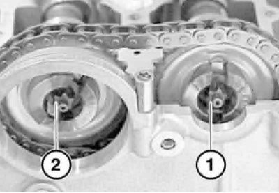
15. Loosen the bolt (1) on the intake camshaft, and then completely unscrew the bolt (2) on the exhaust camshaft.
16. Move the exhaust camshaft sprocket forward, lift the chain (1) above it and remove the sprocket (2) in the direction of the arrow.
17. Unscrew the bolt securing the intake camshaft sprocket and remove the sprocket.
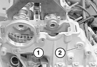
18. Unscrew the support pin (1) of the chain tensioner bar and the support pin (2) of the chain guide.
When installing, replace the removal pins. Pull up the tensioner bar and timing chain guide. Remove tools No.11 6 321, 11 6 322.
To avoid damage to the valves when subsequently installing the camshafts, none of the pistons should be in the TDC position.
19. Remove the engine locking device in the TDC position (No. 11 2 300). Pull the timing chain up and hold it taut so that the engine can be turned. Turn the engine by the vibration damper using special tool No.11 6 480 at an angle of approximately 45° against clockwise.
20. Evenly, in several half-turn steps, unscrew the camshaft bearing cap mounting bolts in sequence from the edges to the middle. Remove the bearing caps and set them aside, arranging them in an order that will allow subsequent installation of the bearing caps in their original places.
21. First remove the intake camshaft, then the exhaust camshaft.
22. Remove all rocker arms (1) and hydraulic valve clearance compensators and arrange them in an order that will allow subsequent installation in their original locations.
23. Remove the bolts.
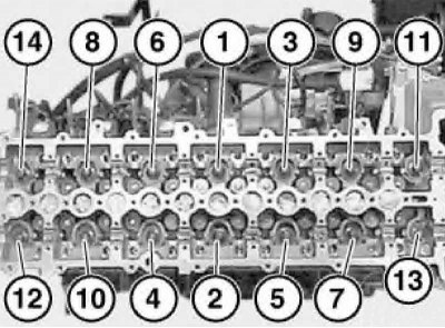
24. Unscrew the cylinder head mounting bolts reverse sequences.
Reuse of cylinder head bolts is not permitted.
Do not damage the glow plugs protruding above the plane of the cylinder head.
25. Remove the glow plugs if necessary.
26. Remove the cylinder head gasket (1), note the number of holes (2) in the gasket. Clean all blind threaded holes (3) from oil, coolant and dirt. Clean the mating surface (4).
Installation
1. If no work has been carried out on the cylinder block that causes a change in the piston bottom protrusion, then it is necessary to use new cylinder head gasket with the same marking (1 cm. illustration) thickness, as on the old gasket. Otherwise, it is necessary to re-determine the repair thickness of the sealing gasket by measuring the protrusion of the bottom of all pistons relative to the plane of the cylinder block. When the protrusion from 0.92 to 1.03 mm use a gasket with 2-my holes, and when protruding more than 1.03 mm - With 3-my holes.
2. Check the centering bushings in the cylinder block for damage and correct installation; replace bushings if necessary.
3. Install new cylinder head gasket and secure the head to the cylinder block new bolts, tightening them in the sequence shown (see illustration).
4. Tighten the bolts (see illustration).
5. Lubricate the camshaft bearing beds and caps with engine oil. Install all rocker arms and hydraulic compensators in their original places.
6. Install the camshafts.
The inlet shaft is marked "E" and the outlet shaft is marked "A"; the bearing caps have the same letter designations, as well as digital designations indicating the location of the cap, counted from the exhaust side. Install the camshaft bearing caps and tighten their mounting bolts.
7. Turn the camshafts by the hexagons so that the tops of the cams of the intake and exhaust valves of the 1st cylinder point towards each other.
8. Install the tensioner bar and timing chain guide and secure them new with your fingers.
9. Center the intake camshaft and secure it using tools No.11 6 321 and 11 6 322 with the piston of the first cylinder at TDC at the end of the compression stroke.
10. Install the fuel rail and high pressure fuel pipes.
11. Place the timing chain on the intake camshaft sprocket, slide the sprocket onto the shaft and secure it with the bolt, tightening it until it fits snugly and then loosening it half a turn.
Any position of the sprocket relative to the camshaft is allowed. Install the exhaust camshaft sprocket in the same way.
12. Install the timing chain guide between the sprockets with a new gasket and tighten the exhaust camshaft sprocket mounting bolt, holding the shaft from turning by the hexagon.
13. Slowly turn the exhaust camshaft clockwise until the timing chain tensioner is fully compressed and remove the tensioner retainer.
14. Loosen the exhaust camshaft sprocket mounting bolt again by half a turn.
15. Tighten the chain tensioner bolt and screw in the tensioner service hole plug with a new sealing ring.
16. Turn the engine clockwise by the vibration damper from the 45° before TDC position to the TDC position.
17. Lock the crankshaft at TDC using special tool No.11 2 300.
18. Install tool No.11 6 321 on the intake camshaft and secure it. Tighten the shaft sprocket mounting bolt using tool No.00 9 120. Tighten the exhaust camshaft sprocket mounting bolt in the same manner.
19. Remove tool No.11 6 321 from the exhaust camshaft.
20. Pull tool No.11 2 300 back just enough to release the flywheel (see illustration).
21. Turn the engine over using tool No.11 6 480 twice in the direction of rotation until the piston of the first cylinder is positioned just before TDC at the end of the compression stroke.
22. Turn the engine in the direction of rotation to the TDC position so that tool No.11 2 300 (locking pin) locked into place with an audible click.
Do not turn the engine in the opposite direction.
23. Lock the crankshaft in the position corresponding to the TDC of the piston of the first cylinder using tool No.11 2 300 (see illustration).
24. Install tool No.11 6 321 on the intake camshaft.
Tool No.11 6 321 must fit snugly against the cylinder head.
25. Install tool No.11 6 321 on the exhaust camshaft so that it fits against the cylinder head without any clearance.
26. Remove tool No.11 6 321 from the exhaust camshaft. Remove tools No.11 6 322 and No.11 2 300.
27. Insert a plug into the service hole to lock the flywheel.
28. Install a new sealing gasket.
29. Install the turbocharger.
Lubricate the threads with copper paste.
30. Install the return pipe and lifting eye (see illustration).
31. Tighten the turbocharger bracket mounting bolts (1).