
Table of contents: Replacing the V-belt of the air…↓ Replacing the alternator drive V-belt ↓
- Home
- BMW 3 Series
- E46
- Power unit
- Engine repair
- Removal, installation and tensioning the V-belt
Removal, installation and tensioning the V-belt (BMW 3 Series E46)
Please also refer to Section Checking the condition of ribbed drive belts.
The crankshaft transmits movement to the coolant pump and generator via a wide ribbed V-belt. In a 6-cylinder engine, the coolant pump shaft is equipped with a radiator fan with a viscous coupling. If there is an air conditioner, its rotation is transmitted to the compressor by an additional ribbed belt. Since the belts are located one behind the other, in order to remove the rear belt, the belt in front of it must first be removed.
Belts are tensioned automatically, no tightening is required. Usually, the service life of the belt is not less than the service life of the car. The belt must be replaced in the following cases:
1. Raise and support the vehicle. Loosen the mounting bolts and remove the lower engine compartment cover, refer to Section Removal and installation the lower engine compartment cover.
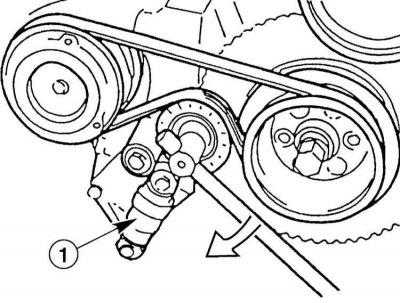
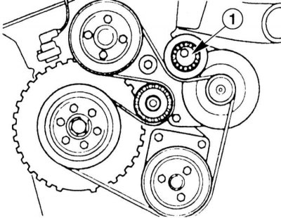
2. Version with hydraulic tensioning element: Insert the socket wrench into the screw on the tension roller. If there is a protective cap, remove it first. As a result of slow clockwise rotation, the hydraulic tensioner "1" is compressed. Remove the V-belt.
3. Version with mechanical tension element: Press the tension element by the hexagon "1" in a clockwise direction. Remove the V-belt.
4. Put the new V-belt on the pulleys. At the same time, turn the tension roller completely to the right, as when removing it. The V-belt should be flush with the pulleys and should not protrude from the side.
5. Slowly release the tension roller. The tension force is determined by the tension member. The tension force value is not adjustable.
6. Install the lower engine compartment cover. Lower the car onto its wheels.
The V-belt drives the generator, coolant pump and power steering pump.
7. Models with air conditioning: Remove the viscous coupling radiator fan, refer to Section Removal and installation a fan with a viscous coupling.

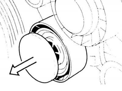
8. Remove the cover from the roller using a screwdriver (arrow on the illustration).
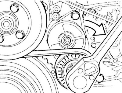
9. Insert the socket wrench into the screw on the tension roller and slowly turn it clockwise (arrows in the illustration). This removes the hydraulic tensioner. Remove the V-belt.
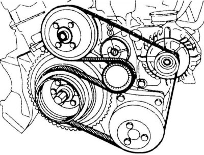
10 Put the new V-belt on the pulleys according to the diagram. In this case, tighten the tension roller as when removing. The V-belt should lie flush with the pulleys and should not protrude from the side.
11. Slowly release the tension roller. The tension force is determined by the tension member. The tension force value is not adjustable.
12. Place the cover on the tension roller.
13. Models with air conditioning: Install the radiator fan, refer to Section Removal and installation a fan with a viscous coupling.
The V-belt drives the generator, coolant pump and power steering pump.
14. Remove the radiator shutters, refer to Section Removal and installation the fan/fan shroud.
15. Insert the 1/2-inch head extension tetrahedron as a lever into the hole on the tensioning element.
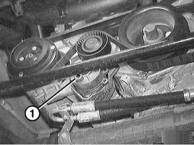
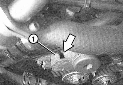
16. Slowly turn the head extension clockwise. This will compress the tension member in the compressed state and insert the rod, such as a drill, through the hole "1" into the hole of the holder.
17. Place the new V-belt on the pulleys as shown in the diagram, compressing the tensioner as shown in the accompanying illustration. The V-belt should lie flush with the pulleys and should not protrude from the sides.
18. Unload the tension roller and remove the lever. The tension force is determined by the tension element. The tension force value is not adjustable. If a rod was used, remove it, which is done by unloading the tension element.
19. Install the radiator shutters, refer to Section Removal and installation the fan/fan shroud.
The crankshaft transmits movement to the coolant pump and generator via a wide ribbed V-belt. In a 6-cylinder engine, the coolant pump shaft is equipped with a radiator fan with a viscous coupling. If there is an air conditioner, its rotation is transmitted to the compressor by an additional ribbed belt. Since the belts are located one behind the other, in order to remove the rear belt, the belt in front of it must first be removed.
Belts are tensioned automatically, no tightening is required. Usually, the service life of the belt is not less than the service life of the car. The belt must be replaced in the following cases:
- Formation of cracks.
- The appearance of noise, for example, when slipping due to oil getting in.
- If there is damage such as: transverse cracks in the ribs, holes in the ribs, dirt deposits and inclusions of small stones between the ribs, fraying or wear of the side surfaces of the rubber ribs, also refer to Section Checking the condition of ribbed drive belts.
If the removed belt is to be used later, it is necessary to mark the direction of rotation on it with chalk.
Replacing the V-belt of the air conditioning compressor drive
The operation of lifting and installing the vehicle on stands is associated with danger! Therefore, before carrying out the operation, read the Section Jacking and towing.
1. Raise and support the vehicle. Loosen the mounting bolts and remove the lower engine compartment cover, refer to Section Removal and installation the lower engine compartment cover.
2. Version with hydraulic tensioning element: Insert the socket wrench into the screw on the tension roller. If there is a protective cap, remove it first. As a result of slow clockwise rotation, the hydraulic tensioner "1" is compressed. Remove the V-belt.
3. Version with mechanical tension element: Press the tension element by the hexagon "1" in a clockwise direction. Remove the V-belt.
4. Put the new V-belt on the pulleys. At the same time, turn the tension roller completely to the right, as when removing it. The V-belt should be flush with the pulleys and should not protrude from the side.
5. Slowly release the tension roller. The tension force is determined by the tension member. The tension force value is not adjustable.
6. Install the lower engine compartment cover. Lower the car onto its wheels.
Replacing the alternator drive V-belt
Models 320i, 323i, 328i
The V-belt drives the generator, coolant pump and power steering pump.
7. Models with air conditioning: Remove the viscous coupling radiator fan, refer to Section Removal and installation a fan with a viscous coupling.
8. Remove the cover from the roller using a screwdriver (arrow on the illustration).
9. Insert the socket wrench into the screw on the tension roller and slowly turn it clockwise (arrows in the illustration). This removes the hydraulic tensioner. Remove the V-belt.
10 Put the new V-belt on the pulleys according to the diagram. In this case, tighten the tension roller as when removing. The V-belt should lie flush with the pulleys and should not protrude from the side.
When designed with additional tension roller "1", the rotation safety device on the axis of the additional tension roller must be fixed in the groove of the generator.
11. Slowly release the tension roller. The tension force is determined by the tension member. The tension force value is not adjustable.
12. Place the cover on the tension roller.
13. Models with air conditioning: Install the radiator fan, refer to Section Removal and installation a fan with a viscous coupling.
Model 320d
The V-belt drives the generator, coolant pump and power steering pump.
14. Remove the radiator shutters, refer to Section Removal and installation the fan/fan shroud.
15. Insert the 1/2-inch head extension tetrahedron as a lever into the hole on the tensioning element.
16. Slowly turn the head extension clockwise. This will compress the tension member in the compressed state and insert the rod, such as a drill, through the hole "1" into the hole of the holder.
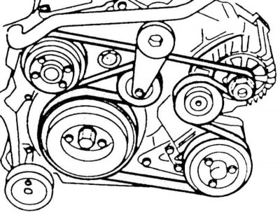
17. Place the new V-belt on the pulleys as shown in the diagram, compressing the tensioner as shown in the accompanying illustration. The V-belt should lie flush with the pulleys and should not protrude from the sides.
The position of the generator may differ from that shown in the accompanying illustration, but the belt routing should be as shown in the illustration.
18. Unload the tension roller and remove the lever. The tension force is determined by the tension element. The tension force value is not adjustable. If a rod was used, remove it, which is done by unloading the tension element.
19. Install the radiator shutters, refer to Section Removal and installation the fan/fan shroud.
This article is available at russian, bulgarian, belarusian, ukrainian, serbian, croatian, romanian, polish, slovak, hungarian
Article verified: Sevastyanov Nikolay
Share information:
Previous articles
БМВ E46: Engine repair
Next articles
Similar articles on other types of BMW cars:
Removal and installation the alternator V-belt / tensioning the V-belt BMW 5 Series E34 (1988-1996)
Removal and installation / tensioning the poly V-belt BMW 5 Series E39 (1995-2003)
Removal and installation the timing belt cover BMW 7 Series E38 (1994-2001)
Cylinder Head Cover — Removal and Installation BMW 7 Series E32 (1986-1994)
Pistons — removal and installation BMW X3 E83 (2003-2010)
Removal and installation the alternator drive belt BMW X5 E53 (1999-2006)
Link in different formats to this page
Visitor comments
No comments yet
- General information
- Manual
- Maintenance
- Power unit
- Engine repair
- Cooling system
- Power system (gasoline)
- Injection system (gasoline)
- Fuel system (diesel)
- Exhaust system
- Ignition system
- Charge and launch systems
- Transmission
- Car gearbox
- Clutch and drive shafts
- Chassis
- Brake system
- Suspension front and rear
- Steering
- Body
- Body care and repair
- Exterior
- Interior
- Electrical equipment
- Troubleshooting
- Lighting and signaling
- Equipment and devices
- Heater and air conditioner
- Electrical circuits
- General information
- Manual
- Repair on the road
- Weekly checks
- Maintenance
- Troubleshooting
- Power unit
- 4 cylinder engines
- 6 cylinder engines
- Engine overhaul
- Cooling and heating
- Fuel and exhaust system
- Starting and charging system
- Ignition system
- Transmission
- Clutch
- Mechanical gearbox
- Automatic gearbox
- Cardan and drive shafts
- Chassis
- Brake system
- Wheel suspension
- Steering
- Body
- Exterior
- Interior
- Electrical equipment
- Equipment and devices
- Electrical circuits
- General information
- Maintenance
- Power unit
- Engine repair
- Cooling system
- Ignition system
- Supply system
- Fuel injection system
- Exhaust system
- Transmission
- Clutch
- Car gearbox
- Front and rear axle
- Chassis
- Steering
- Brake system
- Body
- Exterior
- Interior
- Electrical equipment
- Heating system
- Equipment and devices
- Power devices
- Electrical circuits
- Power unit
- M10/M20 engine
- M40 engine
- Ignition system
- Lubrication system
- Cooling system
- Supply system
- Fuel injection
- Exhaust system
- Transmission
- Clutch
- Manual gearbox
- Front axle
- Rear axle
- Chassis
- Steering
- Brake system
- Body
- Exterior
- Interior
- Electrical equipment
- Heating system
- Equipment and devices
- Electrical circuits
- General information
- Specifications
- Operation and maintenance
- 4-cylinder engine
- Engine repair
- Cooling and lubrication system
- Supply system
- Ignition system
- 6-cylinder engine
- Engine repair
- Cooling and lubrication system
- Supply system
- Fuel injection system
- Ignition system
- Transmission
- Clutch
- 4-speed manual gearbox
- 5-speed manual gearbox
- Automatic gearbox
- Cardan and rear axle
- Chassis
- Steering
- Front suspension
- Rear suspension
- Brake system
- Electrical equipment
- Equipment and devices
- Electrical circuits