
- Home
- BMW 3 Series
- E46
- Power unit
- Engine repair
- Removal and installation the intake manifold
Removal and installation the intake manifold (BMW 3 Series E46)
The intake manifold must be removed, for example, when removing the cylinder head or engine.
1. Disconnect the negative (-) battery cable with the ignition off. The battery is located in the luggage compartment behind the cover on the right side. In BMW 316i, 318i cars, the battery is located in the engine compartment.
2. Remove the air box, refer to Section Removal and installation the air intake box.
3. Disconnect the throttle actuator at the throttle body pipe, refer to Section Removal, installation and adjustment of the throttle actuator.
4. Remove the air hose between the air filter box and the throttle valve pipe by loosening the clamp.
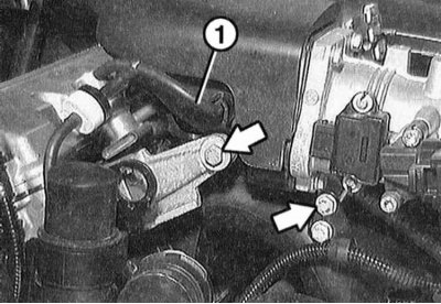
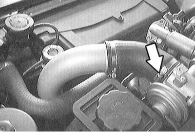
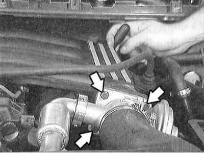
5. Unscrew the bolts securing the upper part of the intake manifold at the front support, as well as at the rear support (arrows in the illustration).
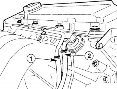
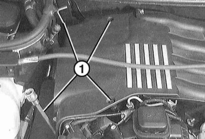
6. Disconnect vacuum hose "1".
7. Disconnect the vacuum hose to the inlet pipe at the brake booster. This will require some force.
8. Loosen the mounting bolts and remove the upper part of the intake manifold.
9. Drain the coolant, refer to Section Replacing the coolant.
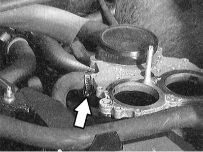
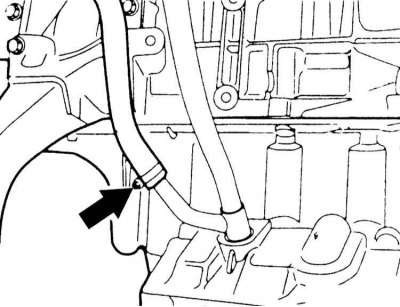
10. Disconnect the coolant hose at the bottom of the intake manifold by loosening the clamp (arrow on the illustration).
11. Disconnect the oil level indicator guide pipe at the bottom of the intake manifold (arrow on the illustration).
12. Open the cable channel at the engine. Disconnect the electrical wires from the following items. Mark the connections with tape to avoid confusion during assembly:
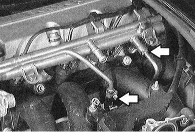
13. Disconnect the fuel supply and return hoses (arrows in the illustration).

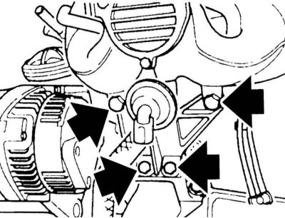
14. Loosen the mounting bolts and disconnect the intake manifold support (arrows in the illustration).
15. Loosen the mounting bolts and disconnect the lower part of the intake manifold at the cylinder head.
1. Replace all O-rings.
2. Tighten the lower intake manifold bolts to the cylinder head in a crisscross pattern evenly to the torque specified in the Specifications.
Secure the intake manifold support with bolts.
3. Secure the fuel supply and return lines.
4. Connect the electrical wires to the following elements:
5. Secure the cable channel to the engine.
6. Secure the oil level indicator guide tube.
7. Place the coolant hose onto the bottom of the intake manifold and secure with a clamp.

8. Secure the top of the intake manifold.
9. Attach the vacuum hose to the inlet manifold on the brake booster.

10. Secure the upper part of the intake manifold to the front support and also to the rear support. Put on the vacuum hose "1".
11. Insert the air hose between the air filter box and the throttle body pipe and secure with clamps.
12. Connect the throttle actuator to the throttle valve pipe, refer to Section Removal, installation and adjustment of the throttle actuator.
13. Reinstall the air collection box, refer to Section Removal and installation the air intake box.
14. Connect the negative (-) battery cable with the ignition off. Set the clock.
1. Disconnect the negative (-) battery cable with the ignition off. The battery is located in the luggage compartment behind the cover on the right side. In BMW 316i, 318i cars, the battery is located in the engine compartment.
2. Remove the air box, refer to Section Removal and installation the air intake box.
3. Disconnect the throttle actuator at the throttle valve pipe, refer to Section Removal, installation and adjustment of the throttle actuator.
4. Remove the air hose between the air filter box and the throttle body pipe by loosening the clamp.
5. Disconnect the idle injector and resonant valve connectors at the throttle valve pipe.
6. Loosen the mounting bolts and remove the cable shaft under the throttle valve pipe.
7. Disconnect the oil drain hose at the oil level indicator guide pipe, after loosening the clamp.
8. Unscrew the guide pipe of the oil level indicator at the inlet manifold.
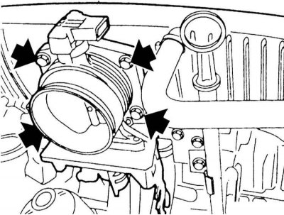
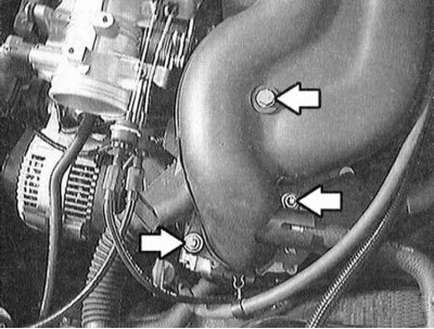
9. Loosen the mounting bolts (arrows in the illustration) and remove the throttle body pipe together with the seal.
10. Remove the oil filler cap. Use a screwdriver to pry off the small caps (arrows in the illustration) and remove. Loosen the bolts underneath. Remove the 2 plastic covers.
11. Remove the oxygen sensor plug connections (arrows in the illustration). Disconnect the VANOS solenoid valve connector.
12. Lift and move aside the injector connector bar.
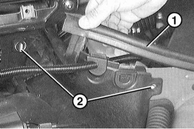
13. Remove the electrical wires from the side trim near the water tank. To do this, lift up the rubber strip "1". Turn the clamps "2" of the side trim 1/4 turn and remove. Lift the side trim up.
14. Disconnect the crankcase ventilation hose. While doing this, squeeze the connection (two arrows on the left).
15. First, disconnect the fuel supply line "1". Then disconnect the fuel return line "2" at the distribution line by loosening the clamps. After removal, the clamps must be replaced.
16. Disconnect the support at the intake manifold.
17. Check that all hoses are disconnected from the inlet manifold.
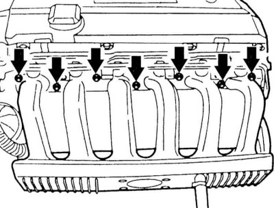
18. Loosen the mounting bolts and remove the intake manifold from the cylinder head (arrows in the illustration). Caution: Make sure that no parts fall into the intake cavities.
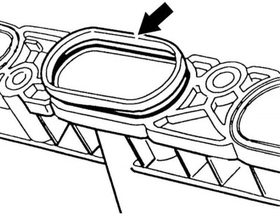
1. Install the intake manifold to the cylinder head and secure it evenly with crosswise bolts. Before installation, check all sealing rings, replace damaged ones.
2. Secure the intake manifold support.
3. Secure the oil level indicator guide pipe to the intake manifold.
4. Place the oil return hose at the level indicator guide pipe and secure it with a clamp.
5. Secure the throttle body pipe with a new sealing ring.
6. Connect the idle injector connector and the throttle body resonant valve.
7. Secure the cable duct under the throttle body pipe.
8. Attach the throttle actuator to the throttle valve pipe and adjust it, refer to Section Removal, installation and adjustment of the throttle actuator.
9. Secure the supply and return fuel lines of the distribution line with new clamps. Install new sealing rings, refer to the "Removal" subsection.
10. Secure the crankcase ventilation connection.
11. Connect the oxygen sensor connector and the VANOS solenoid valve.
12. Put on the injector connector strip.
13. Insert the connector at the water collection compartment. Turn the clamps "1" of the side panel 1/4 turn and fix it.
14. Fasten the two mounting covers. Install the mounting bolt covers.
15. Screw the cap onto the oil filler neck.
16. Install the air collector box, refer to Section Removal and installation the air intake box.
17. Connect the negative (-) battery cable with the ignition off. Set the clock.
1. Disconnect the negative (-) battery cable with the ignition off. The battery is located in the luggage compartment behind the cover on the right side.
2. Remove the air box, refer to Section Removal and installation the air intake box.
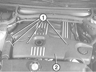
3. Unscrew the mounting bolts "1" and remove the engine trim "2".
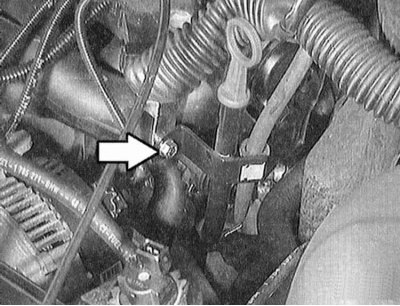
4. Disconnect the suction pipe at the EGR valve (exhaust gas recirculation), why loosen the clamp (arrow on the illustration).
5. Unscrew the mounting bolts "1" and remove the engine cover.
6 Disconnect the hoses from the holders in the area of the oil level indicator.
7. Disconnect the electrical wires from the side trim near the water tank. Remove the rubber strip "1" upwards. Turn the clamps "2" of the side trim 1/4 turn and remove upwards.
8. Unscrew the mounting bolts (arrows in the illustration) and remove the cover on the left side of the engine.
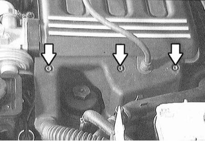
9. Remove the four EGR valve bolts on the intake manifold (arrows in the illustration).
10 Remove the rear intake manifold mounting bolt. The illustration shows a ratchet socket wrench on the rear bolt.
11. Remove the covers between the intake manifold channels.
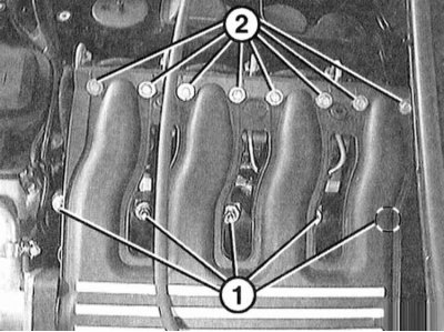
12. Unscrew bolts "1" and nuts "2" at the intake manifold.
1. Replace all O-rings.
2. Fasten the intake manifold to the cylinder head with bolts evenly and crosswise.
3. Further installation is carried out in the reverse order of removal.
4. Install the air collection box, refer to Section Removal and installation the air intake box.
5. Connect the negative (-) battery cable with the ignition off. Set the clock.
Model 316i, 318i (m43TU engine)
Removal
1. Disconnect the negative (-) battery cable with the ignition off. The battery is located in the luggage compartment behind the cover on the right side. In BMW 316i, 318i cars, the battery is located in the engine compartment.
Disconnecting the battery will erase the fault memory of some control units. If necessary, read the fault memory before disconnecting the battery. Refer to Section Troubleshooting. It is advisable to carry out the work in a service station.
2. Remove the air box, refer to Section Removal and installation the air intake box.
3. Disconnect the throttle actuator at the throttle body pipe, refer to Section Removal, installation and adjustment of the throttle actuator.
4. Remove the air hose between the air filter box and the throttle valve pipe by loosening the clamp.
5. Unscrew the bolts securing the upper part of the intake manifold at the front support, as well as at the rear support (arrows in the illustration).
6. Disconnect vacuum hose "1".
7. Disconnect the vacuum hose to the inlet pipe at the brake booster. This will require some force.
8. Loosen the mounting bolts and remove the upper part of the intake manifold.
9. Drain the coolant, refer to Section Replacing the coolant.
10. Disconnect the coolant hose at the bottom of the intake manifold by loosening the clamp (arrow on the illustration).
11. Disconnect the oil level indicator guide pipe at the bottom of the intake manifold (arrow on the illustration).
12. Open the cable channel at the engine. Disconnect the electrical wires from the following items. Mark the connections with tape to avoid confusion during assembly:
- injectors;
- generator, please refer to Section Removal and installation the generator;
- knock sensor on the cylinder block;
- coolant temperature sensor;
- starter, refer to Section Removal and installation, checking of the starter;
- oil level sensor;
- crankshaft position sensor;
- oil pressure indicator sensor.
The engine fuel system is under pressure! Before opening the hose connections, place a thick rag on them. Then, carefully disconnect the hose, relieve the pressure. There is a risk of fire, do not smoke!
13. Disconnect the fuel supply and return hoses (arrows in the illustration).
14. Loosen the mounting bolts and disconnect the intake manifold support (arrows in the illustration).
15. Loosen the mounting bolts and disconnect the lower part of the intake manifold at the cylinder head.
Installation
1. Replace all O-rings.
2. Tighten the lower intake manifold bolts to the cylinder head in a crisscross pattern evenly to the torque specified in the Specifications.
Secure the intake manifold support with bolts.
3. Secure the fuel supply and return lines.
The return pipe clamp must be replaced during installation. Secure the supply pipe with a torque of 20 Nm.
4. Connect the electrical wires to the following elements:
- injectors;
- generator, please refer to Section Removal and installation the generator;
- knock sensor near the cylinder block;
- coolant temperature sensor;
- starter, refer to Section Removal and installation, checking of the starter;
- oil level sensor;
- crankshaft position sensor;
- oil pressure indicator sensor.
5. Secure the cable channel to the engine.
6. Secure the oil level indicator guide tube.
7. Place the coolant hose onto the bottom of the intake manifold and secure with a clamp.
8. Secure the top of the intake manifold.
9. Attach the vacuum hose to the inlet manifold on the brake booster.
10. Secure the upper part of the intake manifold to the front support and also to the rear support. Put on the vacuum hose "1".
11. Insert the air hose between the air filter box and the throttle body pipe and secure with clamps.
12. Connect the throttle actuator to the throttle valve pipe, refer to Section Removal, installation and adjustment of the throttle actuator.
13. Reinstall the air collection box, refer to Section Removal and installation the air intake box.
14. Connect the negative (-) battery cable with the ignition off. Set the clock.
Models 320i, 323i, 328i (engine M52TU)
Removal
1. Disconnect the negative (-) battery cable with the ignition off. The battery is located in the luggage compartment behind the cover on the right side. In BMW 316i, 318i cars, the battery is located in the engine compartment.
Disconnecting the battery will erase the fault memory of some control units. If necessary, read the fault memory before disconnecting the battery. Refer to Section Troubleshooting. It is advisable to carry out the work in a service station.
2. Remove the air box, refer to Section Removal and installation the air intake box.
3. Disconnect the throttle actuator at the throttle valve pipe, refer to Section Removal, installation and adjustment of the throttle actuator.
4. Remove the air hose between the air filter box and the throttle body pipe by loosening the clamp.
5. Disconnect the idle injector and resonant valve connectors at the throttle valve pipe.
6. Loosen the mounting bolts and remove the cable shaft under the throttle valve pipe.
7. Disconnect the oil drain hose at the oil level indicator guide pipe, after loosening the clamp.
8. Unscrew the guide pipe of the oil level indicator at the inlet manifold.
9. Loosen the mounting bolts (arrows in the illustration) and remove the throttle body pipe together with the seal.
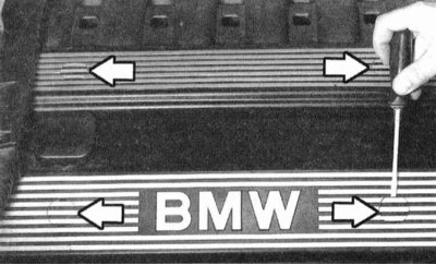
10. Remove the oil filler cap. Use a screwdriver to pry off the small caps (arrows in the illustration) and remove. Loosen the bolts underneath. Remove the 2 plastic covers.
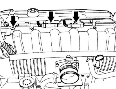
11. Remove the oxygen sensor plug connections (arrows in the illustration). Disconnect the VANOS solenoid valve connector.
12. Lift and move aside the injector connector bar.
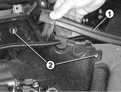
13. Remove the electrical wires from the side trim near the water tank. To do this, lift up the rubber strip "1". Turn the clamps "2" of the side trim 1/4 turn and remove. Lift the side trim up.
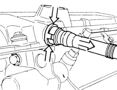
14. Disconnect the crankcase ventilation hose. While doing this, squeeze the connection (two arrows on the left).
The engine fuel system is under pressure! Before opening the hose connections, apply a thick layer of rag to it. Then, carefully disconnect the hose, relieve the pressure. There is a risk of fire, do not smoke!
15. First, disconnect the fuel supply line "1". Then disconnect the fuel return line "2" at the distribution line by loosening the clamps. After removal, the clamps must be replaced.
On some models, the feed line is connected directly to the distribution line. In this case, the sealing ring must be replaced during installation and lubricated with technical petroleum jelly. Fuel hoses can also be secured with clamps. In this case, a special tool BMW-16 1 050 is required to unscrew the clamps. Check the sealing ring before installation. If damaged, replace it, refer to Section Removal and installation of injectors.
16. Disconnect the support at the intake manifold.
17. Check that all hoses are disconnected from the inlet manifold.
18. Loosen the mounting bolts and remove the intake manifold from the cylinder head (arrows in the illustration). Caution: Make sure that no parts fall into the intake cavities.
Installation
1. Install the intake manifold to the cylinder head and secure it evenly with crosswise bolts. Before installation, check all sealing rings, replace damaged ones.
2. Secure the intake manifold support.
3. Secure the oil level indicator guide pipe to the intake manifold.
4. Place the oil return hose at the level indicator guide pipe and secure it with a clamp.
5. Secure the throttle body pipe with a new sealing ring.
6. Connect the idle injector connector and the throttle body resonant valve.
7. Secure the cable duct under the throttle body pipe.
8. Attach the throttle actuator to the throttle valve pipe and adjust it, refer to Section Removal, installation and adjustment of the throttle actuator.
9. Secure the supply and return fuel lines of the distribution line with new clamps. Install new sealing rings, refer to the "Removal" subsection.
10. Secure the crankcase ventilation connection.
11. Connect the oxygen sensor connector and the VANOS solenoid valve.
12. Put on the injector connector strip.
13. Insert the connector at the water collection compartment. Turn the clamps "1" of the side panel 1/4 turn and fix it.
14. Fasten the two mounting covers. Install the mounting bolt covers.
15. Screw the cap onto the oil filler neck.
16. Install the air collector box, refer to Section Removal and installation the air intake box.
17. Connect the negative (-) battery cable with the ignition off. Set the clock.
Model 320d (m47 engine)
Removal
1. Disconnect the negative (-) battery cable with the ignition off. The battery is located in the luggage compartment behind the cover on the right side.
Disconnecting the battery will erase the fault memory of some control units. If necessary, read the fault memory before disconnecting the battery. Refer to Section Troubleshooting. It is advisable to carry out the work in a service station.
2. Remove the air box, refer to Section Removal and installation the air intake box.
3. Unscrew the mounting bolts "1" and remove the engine trim "2".
4. Disconnect the suction pipe at the EGR valve (exhaust gas recirculation), why loosen the clamp (arrow on the illustration).
5. Unscrew the mounting bolts "1" and remove the engine cover.
6 Disconnect the hoses from the holders in the area of the oil level indicator.
7. Disconnect the electrical wires from the side trim near the water tank. Remove the rubber strip "1" upwards. Turn the clamps "2" of the side trim 1/4 turn and remove upwards.
8. Unscrew the mounting bolts (arrows in the illustration) and remove the cover on the left side of the engine.
9. Remove the four EGR valve bolts on the intake manifold (arrows in the illustration).
10 Remove the rear intake manifold mounting bolt. The illustration shows a ratchet socket wrench on the rear bolt.
11. Remove the covers between the intake manifold channels.
12. Unscrew bolts "1" and nuts "2" at the intake manifold.
Installation
1. Replace all O-rings.
2. Fasten the intake manifold to the cylinder head with bolts evenly and crosswise.
3. Further installation is carried out in the reverse order of removal.
4. Install the air collection box, refer to Section Removal and installation the air intake box.
5. Connect the negative (-) battery cable with the ignition off. Set the clock.
This article is available at russian, bulgarian, belarusian, ukrainian, serbian, croatian, romanian, polish, slovak, hungarian
Article verified: Sevastyanov Nikolay
Share information:
Previous articles
БМВ E46: Engine repair
Next articles
Similar articles on other types of BMW cars:
Removal and installation the intake manifold BMW 5 Series E39 (1995-2003)
Removal and installation the intake manifold BMW 5 Series E28 (1981-1988)
Intake manifold — removal and installation BMW 7 Series E32 (1986-1994)
Removal and installation the intake manifold BMW 7 Series E38 (1994-2001)
Pistons — removal and installation BMW X3 E83 (2003-2010)
Intake manifold — design description BMW X5 E53 (1999-2006)
Link in different formats to this page
Visitor comments
No comments yet
- General information
- Manual
- Maintenance
- Power unit
- Engine repair
- Cooling system
- Power system (gasoline)
- Injection system (gasoline)
- Fuel system (diesel)
- Exhaust system
- Ignition system
- Charge and launch systems
- Transmission
- Car gearbox
- Clutch and drive shafts
- Chassis
- Brake system
- Suspension front and rear
- Steering
- Body
- Body care and repair
- Exterior
- Interior
- Electrical equipment
- Troubleshooting
- Lighting and signaling
- Equipment and devices
- Heater and air conditioner
- Electrical circuits
- General information
- Manual
- Repair on the road
- Weekly checks
- Maintenance
- Troubleshooting
- Power unit
- 4 cylinder engines
- 6 cylinder engines
- Engine overhaul
- Cooling and heating
- Fuel and exhaust system
- Starting and charging system
- Ignition system
- Transmission
- Clutch
- Mechanical gearbox
- Automatic gearbox
- Cardan and drive shafts
- Chassis
- Brake system
- Wheel suspension
- Steering
- Body
- Exterior
- Interior
- Electrical equipment
- Equipment and devices
- Electrical circuits
- General information
- Maintenance
- Power unit
- Engine repair
- Cooling system
- Ignition system
- Supply system
- Fuel injection system
- Exhaust system
- Transmission
- Clutch
- Car gearbox
- Front and rear axle
- Chassis
- Steering
- Brake system
- Body
- Exterior
- Interior
- Electrical equipment
- Heating system
- Equipment and devices
- Power devices
- Electrical circuits
- Power unit
- M10/M20 engine
- M40 engine
- Ignition system
- Lubrication system
- Cooling system
- Supply system
- Fuel injection
- Exhaust system
- Transmission
- Clutch
- Manual gearbox
- Front axle
- Rear axle
- Chassis
- Steering
- Brake system
- Body
- Exterior
- Interior
- Electrical equipment
- Heating system
- Equipment and devices
- Electrical circuits
- General information
- Specifications
- Operation and maintenance
- 4-cylinder engine
- Engine repair
- Cooling and lubrication system
- Supply system
- Ignition system
- 6-cylinder engine
- Engine repair
- Cooling and lubrication system
- Supply system
- Fuel injection system
- Ignition system
- Transmission
- Clutch
- 4-speed manual gearbox
- 5-speed manual gearbox
- Automatic gearbox
- Cardan and rear axle
- Chassis
- Steering
- Front suspension
- Rear suspension
- Brake system
- Electrical equipment
- Equipment and devices
- Electrical circuits