
Table of contents: 6-cylinder petrol engine and 520d…↓ Model 520d only ↓
- Home
- BMW 5 Series
- E39
- Power unit
- Engine repair
- Removal and installation the intake manifold
Removal and installation the intake manifold (BMW 5 Series E39)
6-cylinder petrol engine and 520d engine
The intake manifold must be removed, for example, before removing the cylinder head or dismantling the engine. Special instructions for the 520d engine are provided at the end of the chapter.
Removal
Remove the fairing cover.
Disconnect the vacuum hose from the intake manifold that goes to the brake booster (disconnect from the brake booster). Removing the hose requires some force.
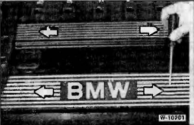
Remove the oil filler cap. Press out the small "arrow" plugs with a screwdriver and unscrew the bolts located underneath. Remove both plastic covers.
Disconnect the plug connectors for the oxygen sensors. Disconnect the plug from the VAN0S solenoid valve.
Remove the multi-socket connector for the valve injectors and set it aside.
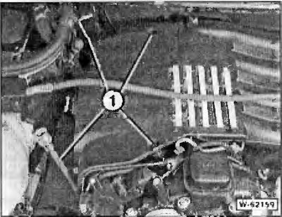
Remove the cover from the intake manifold. Unscrew contact "1" for connecting the positive terminal of the storage battery and squeeze the 2 clamps "arrows". Unfasten the base by moving it downwards.
Disconnect the crankcase ventilation system line.
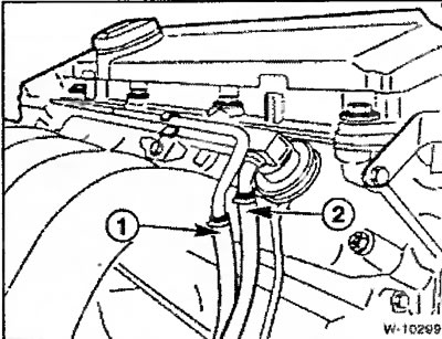
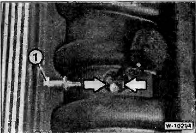
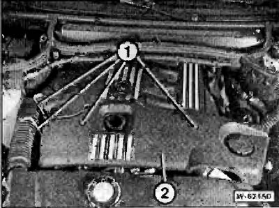
Warning: Fire hazard, no smoking. Collect protruding fuel with a rag. Loosen the clamps and disconnect the fuel supply hose "1" first (from the filter), then the fuel outlet hose "2" from the fuel distributor. After loosening, always replace the hose clamps with new ones.
Note: On some models, the fuel supply hose is attached directly to the fuel distributor. In this case, always replace the sealing ring with a new one and lubricate it with technical petroleum jelly before installation. There is also a version in which the fuel hoses are attached using fixing clamps - in this case, a special tool from BMW 161 050 is required to release the clamps. Check the condition of the sealing ring before installing, damaged ring lure.
Unscrew the fasteners throttle valve pipe.
Caution: Do not disconnect the throttle linkage and coolant hoses of the throttle preheating system.
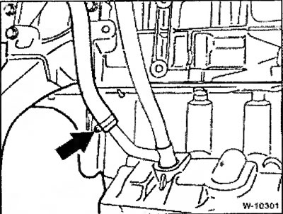
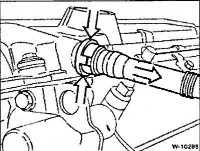
Loosen the clamp and disconnect the oil return hose at the engine oil level indicator guide tube.
Loosen the oil level indicator guide tube fastening to the intake manifold.
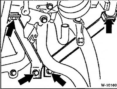
Loosen the intake manifold support and coolant line retaining bracket.
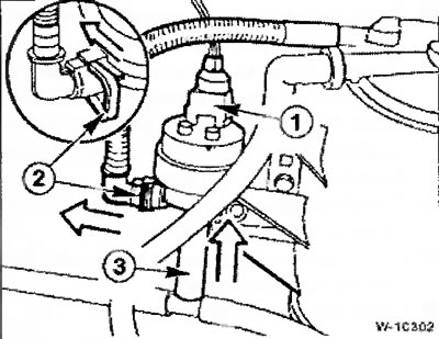
Disconnect plug connector "1" at the fuel tank ventilation system valve. Pull the valve out of the holder by moving it upwards. Press clamp "2" and disconnect the hose. Disconnect the plug connectors of the intake air temperature sensor and the idle speed control valve at the intake manifold.
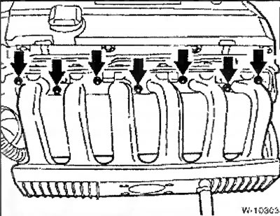
Loosen the intake manifold fastening to the cylinder head.
Caution: Make sure that no parts fall into the intake ports, as this may cause serious damage to the engine.
Installation
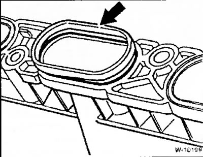
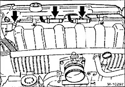
Place the intake manifold on the cylinder head and tighten the fittings evenly using a cross method. Before installation, check all sealing rings "arrow", replace damaged rings with new ones.
Tighten the intake manifold support.
Connect the plug connectors of the intake air temperature sensor and the idle speed control valve at the intake manifold.
Insert the fuel tank ventilation system valve and secure the hose.
Attach the positive battery terminal socket to the intake manifold and screw in the Allen key. Replace the cover.
Screw the oil level indicator guide tube to the intake manifold.
Connect the oil return hose to the engine oil level indicator guide tube and secure it with a clamp.
Install throttle body pipe.
Connect the fuel supply and return hoses to the fuel distributor and secure them with new clamps. When securing the hoses to the fuel distributor, proceed in accordance with the existing design, see "Removal".
Connect the crankcase ventilation system line.
Connect the plug connectors for the oxygen sensors and the VANOS solenoid valve.
Install the multi-socket connector for the valve injectors.
Attach the brake booster vacuum hose to the intake manifold.
Install and screw both plastic trims. Replace the bolt caps.
Tighten the oil filler cap.
Install the fairing.
Model 520d only
Removal
Remove the fairing.
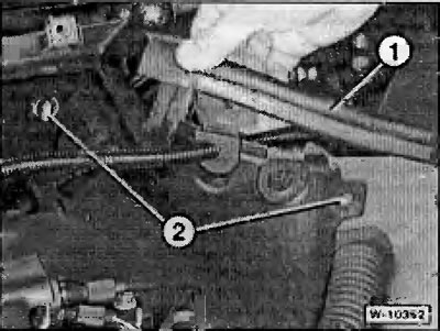
Unscrew bolts "1" and remove engine trim "2".
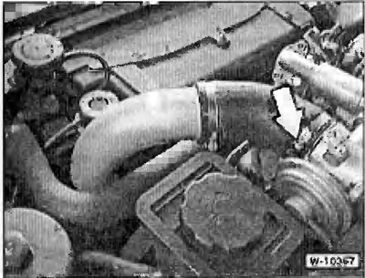
Loosen the clamp "arrow" and disconnect it from the AGR valve (exhaust gas recirculation system valves) air intake pipe.
Unscrew bolts "1" and remove the engine cover.
Unclip the hoses located in the area of the engine oil level indicator from the holders.
Unfasten the pipes from the side paneling at the water drainage casing. Remove the rubber pad "1" by moving it upwards. Release the rotary clamps of the side paneling "2" by turning them ¼ of a turn. Pull the side paneling out by moving it upwards.
Unscrew the "arrow" bolts and remove the cover on the left side of the engine.
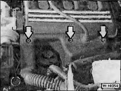
Remove the 4 "arrow" bolts securing the AGR valve to the intake manifold.
Note: The 4th bolt is not visible in the picture.
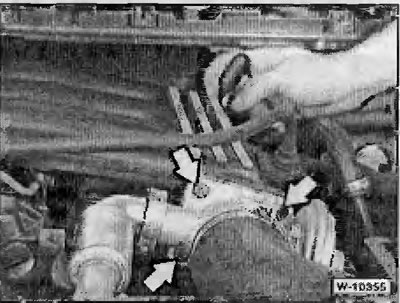
Remove the rear bolt on the intake manifold. In Figure W-10355, a socket wrench with a ratchet is placed against the rear bolt.
Remove the covers located between the intake manifold channels.
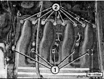
Unscrew bolts and nuts "1" and "2" securing the intake manifold. Remove the manifold.
Installation
Replace all sealing rings
Tighten the intake manifold to the cylinder head evenly in a crisscross pattern.
Further installation is carried out in reverse order.
Install the fairing.
This article is available at russian, bulgarian, belarusian, ukrainian, serbian, croatian, romanian, polish, slovak, hungarian
Article verified: Ilyinsky Matvey
Share information:
Previous articles
БМВ E39: Engine repair
Next articles
Removal and installation the lower engine compartment casing
Key engine characteristics
Diesel engine M51 (525tds)
Petrol engine M52 (520i, 523i, 528i)
General information about engines
Key engine characteristics
Diesel engine M51 (525tds)
Petrol engine M52 (520i, 523i, 528i)
General information about engines
Removal and installation the cylinder head / replacing the cylinder…
Removal and installation the cylinder head (only M52TU engine…
Removal and installation the cylinder head — model 525tds
Removal and installation the cylinder head — 520d models only (M47…
Removal and installation the camshaft — 6-cylinder petrol engine
Removal and installation the cylinder head (only M52TU engine…
Removal and installation the cylinder head — model 525tds
Removal and installation the cylinder head — 520d models only (M47…
Removal and installation the camshaft — 6-cylinder petrol engine
Similar articles on other types of BMW cars:
Removal and installation the intake manifold BMW 3 Series E46 (1998-2006)
Removal and installation the air intake BMW 3 Series E36 (1990-2000)
Intake manifold — removal and installation BMW 7 Series E32 (1986-1994)
Removal and installation the intake manifold BMW 7 Series E38 (1994-2001)
Pistons — removal and installation BMW X3 E83 (2003-2010)
Intake manifold — design description BMW X5 E53 (1999-2006)
Link in different formats to this page
Visitor comments
No comments yet
- General information
- Governing bodies
- Manual
- Maintenance
- Power unit
- Engine repair
- Lubrication system
- Cooling system
- Ignition system
- Supply system
- Injection system (gasoline)
- Injection system (diesel)
- Exhaust system
- Transmission
- Clutch
- Car gearbox
- Front axle
- Rear axle
- Chassis
- Steering
- Brake system
- Wheels and tires
- Body
- Interior
- Exterior
- Heating system
- Electrical equipment
- Equipment and devices
- Power devices
- Windscreen wipers
- Electrical circuits
- General information
- Manual
- Maintenance
- Power unit
- Engine repair
- Ignition system
- Engine lubrication system
- Cooling system
- Fuel system (gasoline)
- Fuel system (diesel)
- Exhaust system
- Transmission
- Clutch
- Car gearbox
- Chassis
- Front and rear suspension
- Steering
- Brake system
- Body
- Exterior
- Interior
- Electrical equipment
- Heating system
- Equipment and devices
- Power devices
- Electrical circuits
- General information
- Manual
- Maintenance
- Power unit
- Engine in a car
- Engine overhaul
- Cooling system
- Supply system
- Ignition system
- Control system
- Transmission
- Clutch
- Manual gearbox
- Automatic gearbox
- Transmission line
- Chassis
- Steering
- Front suspension
- Rear suspension
- Brake system
- Body
- Body elements
- Car care and painting
- Electrical equipment
- Heater and air conditioner
- Equipment and devices
- Starter and generator
- Electrical circuits
- General information
- Operation and maintenance
- Specifications
- Power unit
- Engine repair
- Cooling and lubrication system
- Supply system
- Ecotronic power supply system
- Fuel injection system
- Ignition system
- Transmission
- Clutch
- Gearbox BMW 242/4
- Gearbox Getrag 262/8
- Gearbox Getrag 265/6
- Automatic gearbox
- Cardan gear
- Rear axle
- Chassis
- Steering
- Front suspension
- Rear suspension
- Brake system
- Electrical equipment
- Equipment and devices
- Electrical circuits