
Table of contents: Removal ↓ Installation ↓
- Home
- BMW 5 Series
- E39
- Power unit
- Engine repair
- Removal and installation the cylinder head — 520d models only (M47 engine)
Removal and installation the cylinder head — 520d models only (M47 engine) (BMW 5 Series E39)
Removal
Caution: The operating procedures and instructions applicable to all diesel engines are given in the chapter dedicated to the 525tds engine. Only the differences that apply to the 520d engine are described below. The tightening method for the cylinder head bolts is also valid for the 530d engine, the tightening sequence is the same as for the 525tds engine.
Cylinder head gasket defect is determined by several signs.
Since removing the cylinder head is quite labor-intensive and is performed using a special BMW tool, it is recommended to contact a BMW service station to perform the work.
Remove the intake manifold.
Remove the replacement element engine air filter.
Remove the fuel lines high pressure and nozzles.
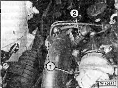
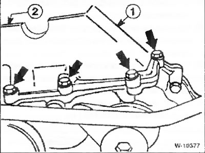
Unscrew bolts "1" and remove the inlet pipe.
Disconnect plug connector "2" by pressing the wire lock of the plug down.
Loosen the cylinder head cover mounting bolts in a crosswise manner in the sequence from 22 to 1, see below Fig. W-10372.
Drain the coolant, including from engine cylinder block.
Use a screwdriver to press the wire clamps and disconnect the coolant hoses leading to the radiator from the thermostat housing.
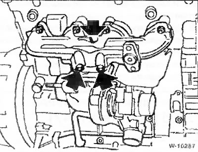
Loosen the turbocharger mount to the exhaust manifold "arrow".
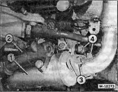
Remove the AGR system cooler "1" together with the thermostat. To do this, loosen the coolant hose clamps under the AGR system cooler and disconnect the hoses. Unscrew the flange mounting bolts "3" and the bracket bolts "4" on both sides of the AGR system cooler.
Loosen the fastening of the coolant pipe to the cylinder head located under the thermostat housing. Loosen the fastening of the pipe to the cylinder head bracket.
Remove both camshafts.
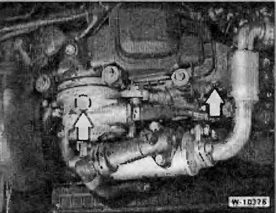
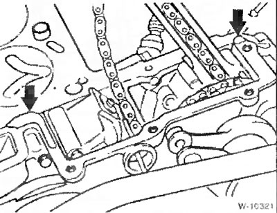
In the places marked by the "arrows", unscrew the support pins of the film of the chain guide and tensioner.
Note: The left finger in the picture is covered by a vacuum pump.
Pull the tensioner bar out with an upward movement.
Unscrew the bolts securing the "arrow" of the chain shaft. Also unscrew the bolts "1" and "2" not visible in the picture.
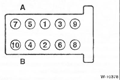
Loosen the cylinder head mounting bolts by ½ turn in the sequence from 10 to 1. Then completely unscrew the bolts in the same sequence. A - intake side; B - release side.
With the help of an assistant, remove the cylinder head.
Caution: Do not place the removed cylinder head with the sealing surface facing down, as this may damage the glow plugs. Place the cylinder head on two wooden supports.
Installation
Caution: Machining of the cylinder head sealing surface is not permitted.
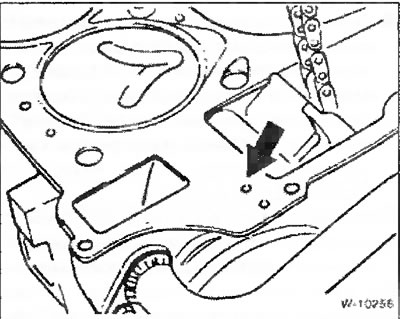
Place the new cylinder head gasket dry and on a dry surface so that the holes in the head and cylinder block are not covered. Depending on the thickness, the gasket is marked with a different number of holes "arrow". The new gasket must be the same thickness (with the same number of holes), that and the removed gasket.
Note: the gaps in the joints between the chain shaft and the cylinder head do not need to be sealed with sealant. There are additional sealing strips "arrows" on the sealing gasket in these places.
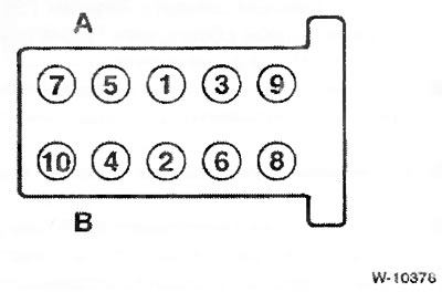
The cylinder head bolts are tightened in 5 stages. In each stage, the bolts are tightened in sequence from 1 to 10. A - intake side; B - release side.
- Step 1: Using a torque wrench, tighten the bolts to 80 Nm.
- Step 2: Using the locked key, loosen the bolts again by 180° (½ turn).
- Step 3: Using a torque wrench, tighten the bolts to 50 Nm.
- Step 4: Using the locked key, turn it an additional 90° (¼ turn).
- Step 5: Using the locked key, turn it an additional 90° (¼ turn).
Screw in and tighten the chain shaft mounting bolts to 15 Nm.
Screw in 2 new support pins with new sealing rings for the tensioner and guide bars. The support pins must be replaced because the threads are covered with a micro-shell and are therefore self-locking.
Screw the sprocket with the chain attached to the camshaft, do not tighten the mounting bolt too much.
Attention: The contact surfaces of the mating parts must be free of grease and must be clean.
Remove the chain tensioner locking pin and thereby create chain tension. Screw the plug into the cylinder head into the hole for the locking pin.
Install the camshafts.
Screw the coolant pipe with a new sealing gasket under the thermostat housing to the cylinder head.
Screw on the EGR system cooler with new flange joint sealing gaskets. Put on the coolant hoses and secure them with clamps.
Connect the hoses to the thermostat housing and secure them.
Screw the turbocharger with a new sealing gasket to the exhaust manifold with new self-locking nuts. Lubricate the bolts with copper beforehand (high temperature) grease. Tighten the nuts to a torque of 45 Nm.
Always install a new cylinder head cover gasket.
Apply a bead of Drei Bond 1209 or Loctite Ultra Black sealant approximately 2 mm high and wide to the non-corner joints of the cylinder head cover sealing surface in the area between the cylinder head and the vacuum pump.
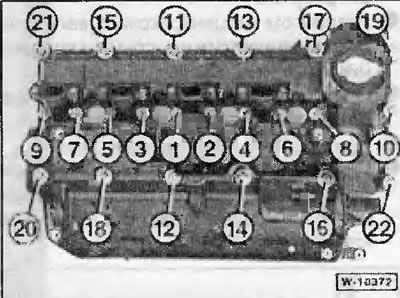
First tighten the cylinder head cover mounting bolts by hand in a crosswise manner in the sequence from 22 to 1. Then, in the second step in the same sequence, tighten the bolts to a torque of 15 Nm.
Connect and secure the plug connector to the mass air flow meter.
Fasten the inlet pipe with two bolts, see above drawing W-10371.
Install the injectors and high pressure fuel lines.
Install the intake manifold.
Install replacement engine air filter element.
This article is available at russian, bulgarian, belarusian, ukrainian, serbian, croatian, romanian, polish, slovak, hungarian
Article verified: Ilyinsky Matvey
Share information:
Previous articles
БМВ E39: Engine repair
Next articles
Similar articles on other types of BMW cars:
Removal and installation the cylinder head. Models 318tds/325td… BMW 3 Series E36 (1990-2000)
Removal and installation the cylinder head BMW 3 Series E30 (1982-1994)
Cylinder head of the M70 series gasoline engine — removal and… BMW 7 Series E32 (1986-1994)
Removal and installation cylinder head covers BMW 7 Series E38 (1994-2001)
Removal and installation the cylinder head BMW X3 E83 (2003-2010)
Removal and installation the engine BMW X5 E53 (1999-2006)
Link in different formats to this page
Visitor comments
No comments yet
- General information
- Governing bodies
- Manual
- Maintenance
- Power unit
- Engine repair
- Lubrication system
- Cooling system
- Ignition system
- Supply system
- Injection system (gasoline)
- Injection system (diesel)
- Exhaust system
- Transmission
- Clutch
- Car gearbox
- Front axle
- Rear axle
- Chassis
- Steering
- Brake system
- Wheels and tires
- Body
- Interior
- Exterior
- Heating system
- Electrical equipment
- Equipment and devices
- Power devices
- Windscreen wipers
- Electrical circuits
- General information
- Manual
- Maintenance
- Power unit
- Engine repair
- Ignition system
- Engine lubrication system
- Cooling system
- Fuel system (gasoline)
- Fuel system (diesel)
- Exhaust system
- Transmission
- Clutch
- Car gearbox
- Chassis
- Front and rear suspension
- Steering
- Brake system
- Body
- Exterior
- Interior
- Electrical equipment
- Heating system
- Equipment and devices
- Power devices
- Electrical circuits
- General information
- Manual
- Maintenance
- Power unit
- Engine in a car
- Engine overhaul
- Cooling system
- Supply system
- Ignition system
- Control system
- Transmission
- Clutch
- Manual gearbox
- Automatic gearbox
- Transmission line
- Chassis
- Steering
- Front suspension
- Rear suspension
- Brake system
- Body
- Body elements
- Car care and painting
- Electrical equipment
- Heater and air conditioner
- Equipment and devices
- Starter and generator
- Electrical circuits
- General information
- Operation and maintenance
- Specifications
- Power unit
- Engine repair
- Cooling and lubrication system
- Supply system
- Ecotronic power supply system
- Fuel injection system
- Ignition system
- Transmission
- Clutch
- Gearbox BMW 242/4
- Gearbox Getrag 262/8
- Gearbox Getrag 265/6
- Automatic gearbox
- Cardan gear
- Rear axle
- Chassis
- Steering
- Front suspension
- Rear suspension
- Brake system
- Electrical equipment
- Equipment and devices
- Electrical circuits