
Table of contents: Removal ↓ Installation ↓
- Home
- BMW 3 Series
- E36
- Power unit
- Engine repair
- Removal and installation the cylinder head. Models 318tds/325td (Engine M51/M52)
Removal and installation the cylinder head. Models 318tds/325td (Engine M51/M52) (BMW 3 Series E36)
The four-cylinder diesel engine M51 can be considered as a shortened six-cylinder engine M52. A description of the removal of the six-cylinder engine is given. Special instructions are given for the four-cylinder engine.
Disconnect the ground wire from the battery.
Drain the coolant from the engine by unscrewing the drain plug on the side of the engine block under the exhaust manifold. After draining, immediately screw the plug back on and tighten it.
Loosen the intake manifold mounting bolts and remove the mount.
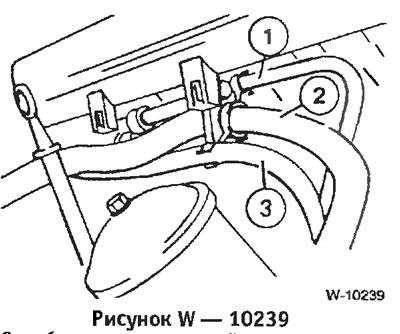
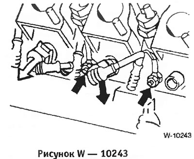
Release the following hoses from the mountings on the cylinder head: 1 - brake booster vacuum hose; 2 - heater water hose; 3 - fuel hose to the high pressure fuel pump.
Disconnect the vacuum hose from the intake manifold (on the exhaust gas recirculation valve).
Disconnect the temperature sensor connector on the intake manifold by pressing the wire clip.
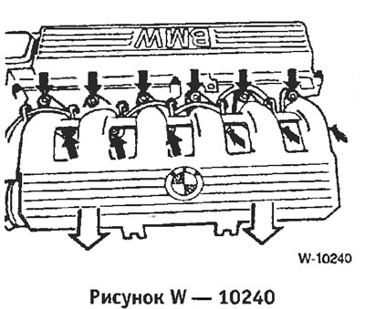
Unscrew the intake manifold.
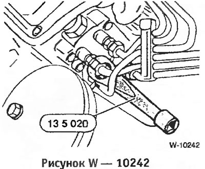
Loosen the union nuts of the injection pipes on the injectors and on the high-pressure fuel pump. This requires a special BMW or HAZET key No.4550. Close the holes with plugs.
Disconnect the wires from the glow plugs.
Remove the V-belt.
Unbolt the front muffler pipe from the turbocharger. On a four-cylinder engine, unbolt the turbocharger from the front muffler pipe.
Loosen the cylinder head bolt covers first by ½ turn and then remove them. There are only 6 bolts on a four-cylinder engine. Remove the cylinder head cover.
Unscrew the hydraulic V-belt tensioner and disconnect the damper. Caution: Store the removed tensioner only in the installation position, i.e. standing. Otherwise, malfunctions may occur.
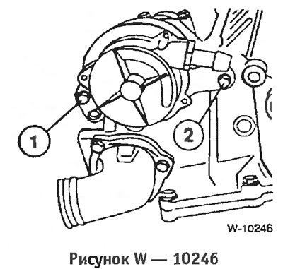
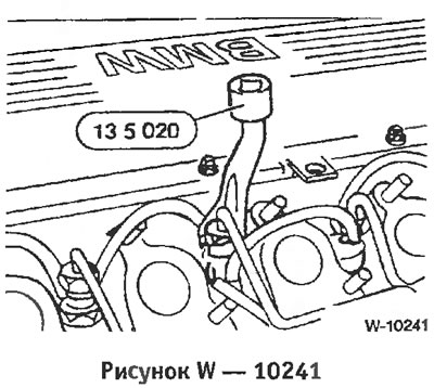
Loosen 2 bolts and remove the vacuum pump. Bolt "2" also serves to secure the chain guide. Since the bolt thread must be sealed, coat the thread of the new bolt with sealing compound. After each loosening, either replace the bolt or coat it with regular liquid sealing compound.
Set the engine to the top dead center position of cylinder 1. To do this, engage 5th gear and move the car forward on a level surface or turn the crankshaft pulley in the direction of engine rotation to a position in which the camshaft cams of the intake and exhaust valves of the first cylinder (from the drive chain side) will be directed towards each other.
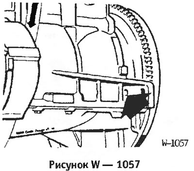
Fix the crankshaft in the top dead center position using the BMW 11 2 300 device or another suitable rod. To do this, insert the rod through the hole in the engine block into the hole in the flywheel.
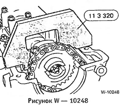
Fix the camshaft with the BMW device. You can do without the device when unscrewing the camshaft sprocket, holding the camshaft by the 27 mm hexagon.
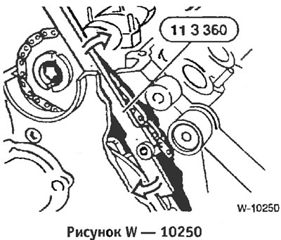
Insert the appropriate clamping lever into the chain tensioner bar and press the tensioner.
Unscrew the plug and fix the tensioner in a compressed state with the appropriate rod.
Unscrew the tension bar retaining pin from the cylinder head and remove the O-ring.
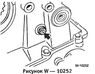
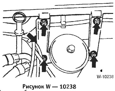
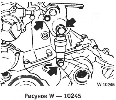
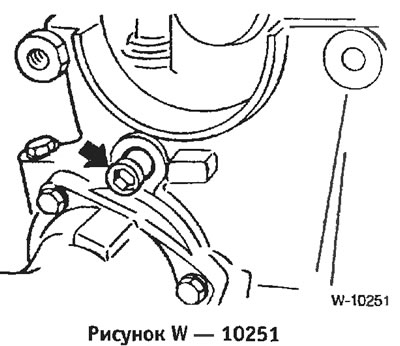
Unscrew the gearbox cover bolts. Fastening "1" is made in the form of a stud and nut.
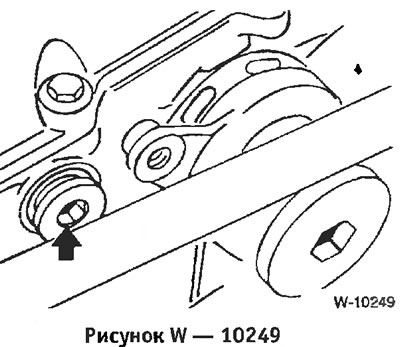
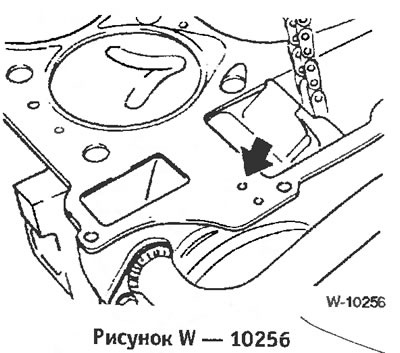
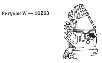
Unscrew the bolt "arrow" and also disconnect the drain hose from the nozzle.
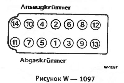
Ansaugkrummer — Intake manifold
Abgaskrummer — Intake manifold
In sequence 14 to 1, first loosen the cylinder head bolts ½ turn and then remove them. A Torx head bolt key of size E12 is required to loosen the cylinder head bolts.
Remove the cylinder head.
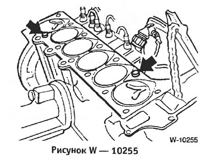
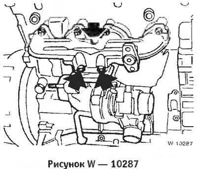
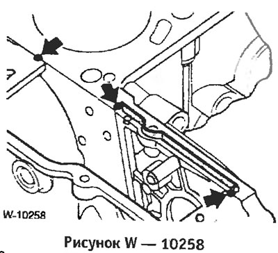
Before installation, clean the cylinder head and engine block from seal residues. Seal residues should not get into the holes, cover the holes with rags. Check the position of the centering bushings "arrows".
Measure the flatness of the cylinder head and engine block with a steel ruler in the longitudinal and transverse directions. Note: The cylinder head cannot be milled. If there are any comments, it should be replaced. Check the cylinder head for cracks and its working surfaces for scratches.
Thoroughly clean the cylinder head bolt holes from oil and other objects.
Be sure to replace the cylinder head gasket.
Lubricate the joints of the gearbox cover with the cylinder head with sealing compound "Drei Bond 1209".
Apply a new gasket without sealing compound so that it does not cover the holes. The gasket has a different number of marking holes depending on its thickness. The new gasket must have the same thickness (the same number of marking holes), that and the removed gasket.
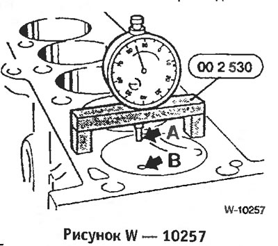
If it is unclear which gasket to install, for example after repairing the engine block, measure the piston protrusions. The gasket thickness is selected based on the maximum protrusion of one of the 6 pistons. To measure, place the dial indicator at point "A" and, by slightly turning the crankshaft in both directions, determine the highest position. Then repeat the measurement at point "B". The average value between the measurement results at points "A" and "B" gives the "piston protrusion" value. These measurements are carried out on all 4 or 6 pistons, respectively.
The average value is determined based on 6 results. That is, all the results should be added up and the sum divided by 4 or 6, respectively. If the value is less than 0.76 mm, a gasket with 2 holes should be installed. If the value is higher than 0.76 mm, a gasket with 3 holes should be installed.
Install the cylinder head.
Insert and tighten the cylinder head bolts by hand, lubricated with engine oil.
Four-cylinder diesel engine:
Six-cylinder engine (Figure W 1097):
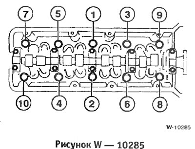
The cylinder head bolts are tightened in 6 passes. In each pass, tightening is performed in sequence from 1 to (Four-cylinder engine: 1 to 10)
Replace the sealing gasket on the high-pressure fuel pump. Apply an elastic sealing compound, such as "3 Bond 1209".
Install the gearbox cover and tighten the bolts to a torque of 10 Nm.
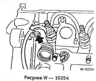
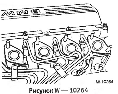
Tighten the fasteners near the injector and also put the return fuel hose on the injector (Figure W 10254).
Screw in the 2 tension bar and chain guide retaining pins with new O-rings.
Screw the sprocket with the chain attached to the camshaft; do not tighten the bolt yet.
Remove the locking pin from the chain tensioner so that the chain is taut. Screw the plug into the hole in the cylinder head.
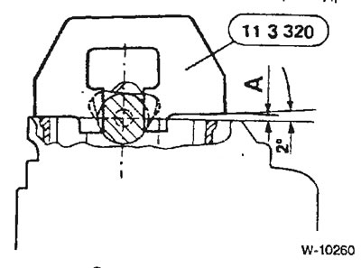
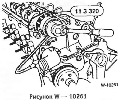
Only if the camshaft is locked using the BMW adjustment template: The template is designed for adjusting chains with a mileage of up to approximately 20,000 km. For chains with higher mileage, a shim (feeler gauge) with a thickness of A = 4.61 mm should be installed on the intake side of the cylinder head. If the template is not used, turn the camshaft approximately 2 to the left and hold it in this position by the 27 mm Allen key.
In this position, tighten the camshaft sprocket in 2 passes:
Insert the vacuum pump into the place with the O-ring, the rod should engage with the cutout in the camshaft sprocket.
Tighten the 2 vacuum pump bolts to 20 Nm. Either replace the inner bolt with a new one or coat it with a regular liquid sealant.
Insert the shock absorber and V-belt tensioner bracket and tighten.
Install the V-belt.
Check the integrity of the cylinder head cover gasket and replace if necessary.
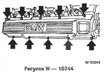
Install the cylinder head cover and tighten the bolts crosswise from the inside out to a torque of 15 Nm. Ensure that the gasket is correctly positioned in the cutouts, see figure.
Six-cylinder engine: Bolt the front muffler pipe with a new gasket and new self-locking nuts to the turbocharger. Pre-coated the bolts with copper (high temperature) paste. First tighten all the bolts to a tightening torque of 30 Nm, and then tighten them to a torque of 50 Nm. In the version with pressure springs, tighten the nuts to a spring length of 27 mm.
Four-cylinder engine: Bolt the turbocharger with a new gasket and new self-locking nuts to the front muffler pipe. Pre-coated the bolts with copper (high temperature) paste. Tighten all bolts to a tightening torque of 45 Nm
Connect the wires to the glow plugs. Push the connectors until they snap into place.
Insert the injection tubes without bending them. Tighten the union nuts with a special wrench to a torque of 20 Nm.
Replace the intake manifold gaskets. Then install the intake manifold, tighten the bolts crosswise to 25 Nm.
Tighten the intake manifold support mounting bolts.
Route all hoses through the intake manifold mount and connect them.
Connect the electrical wires.
Connect the ground wire to the battery.
Fill with coolant.
Check the engine oil level, top up if necessary. If the cylinder head was removed to replace a blown cylinder head gasket, it is recommended to change the oil and replace the oil filter, as coolant may have gotten into the oil.
Install the cylinder head cover and tighten the bolts crosswise in sequence from inside to outside to a torque of 15 Nm.
[Information taken from this resource BMWMAN.ru]
Removal
Disconnect the ground wire from the battery.
Caution: When the battery is disconnected, the information in the electronic memory devices, such as the engine fault memory or the radio security code memory, is erased. When disconnecting the battery, follow the instructions in the "Radio" and "Removing and installing the battery" sections.
Drain the coolant from the engine by unscrewing the drain plug on the side of the engine block under the exhaust manifold. After draining, immediately screw the plug back on and tighten it.
Loosen the intake manifold mounting bolts and remove the mount.
Release the following hoses from the mountings on the cylinder head: 1 - brake booster vacuum hose; 2 - heater water hose; 3 - fuel hose to the high pressure fuel pump.
Disconnect the vacuum hose from the intake manifold (on the exhaust gas recirculation valve).
Disconnect the temperature sensor connector on the intake manifold by pressing the wire clip.
Unscrew the intake manifold.
Loosen the union nuts of the injection pipes on the injectors and on the high-pressure fuel pump. This requires a special BMW or HAZET key No.4550. Close the holes with plugs.
Disconnect the wires from the glow plugs.
Remove the V-belt.
Unbolt the front muffler pipe from the turbocharger. On a four-cylinder engine, unbolt the turbocharger from the front muffler pipe.
Loosen the cylinder head bolt covers first by ½ turn and then remove them. There are only 6 bolts on a four-cylinder engine. Remove the cylinder head cover.
Unscrew the hydraulic V-belt tensioner and disconnect the damper. Caution: Store the removed tensioner only in the installation position, i.e. standing. Otherwise, malfunctions may occur.
Loosen 2 bolts and remove the vacuum pump. Bolt "2" also serves to secure the chain guide. Since the bolt thread must be sealed, coat the thread of the new bolt with sealing compound. After each loosening, either replace the bolt or coat it with regular liquid sealing compound.
Set the engine to the top dead center position of cylinder 1. To do this, engage 5th gear and move the car forward on a level surface or turn the crankshaft pulley in the direction of engine rotation to a position in which the camshaft cams of the intake and exhaust valves of the first cylinder (from the drive chain side) will be directed towards each other.
Fix the crankshaft in the top dead center position using the BMW 11 2 300 device or another suitable rod. To do this, insert the rod through the hole in the engine block into the hole in the flywheel.
Fix the camshaft with the BMW device. You can do without the device when unscrewing the camshaft sprocket, holding the camshaft by the 27 mm hexagon.
Insert the appropriate clamping lever into the chain tensioner bar and press the tensioner.
Unscrew the plug and fix the tensioner in a compressed state with the appropriate rod.
Unscrew the tension bar retaining pin from the cylinder head and remove the O-ring.
Unscrew the gearbox cover bolts. Fastening "1" is made in the form of a stud and nut.
Unscrew the bolt "arrow" and also disconnect the drain hose from the nozzle.
Ansaugkrummer — Intake manifold
Abgaskrummer — Intake manifold
In sequence 14 to 1, first loosen the cylinder head bolts ½ turn and then remove them. A Torx head bolt key of size E12 is required to loosen the cylinder head bolts.
Remove the cylinder head.
Caution: Do not place the cylinder head on the contact surface after removal, otherwise the fully open valves may be damaged. Therefore, the cylinder head should be placed on 2 wooden pads.
Installation
Before installation, clean the cylinder head and engine block from seal residues. Seal residues should not get into the holes, cover the holes with rags. Check the position of the centering bushings "arrows".
Measure the flatness of the cylinder head and engine block with a steel ruler in the longitudinal and transverse directions. Note: The cylinder head cannot be milled. If there are any comments, it should be replaced. Check the cylinder head for cracks and its working surfaces for scratches.
Thoroughly clean the cylinder head bolt holes from oil and other objects.
Caution: There must be no oil in the recesses, otherwise the bolts will not tighten the cylinder head completely, even though they are tightened to the required torque. In addition, the engine block may crack.
Be sure to replace the cylinder head gasket.
Lubricate the joints of the gearbox cover with the cylinder head with sealing compound "Drei Bond 1209".
Apply a new gasket without sealing compound so that it does not cover the holes. The gasket has a different number of marking holes depending on its thickness. The new gasket must have the same thickness (the same number of marking holes), that and the removed gasket.
If it is unclear which gasket to install, for example after repairing the engine block, measure the piston protrusions. The gasket thickness is selected based on the maximum protrusion of one of the 6 pistons. To measure, place the dial indicator at point "A" and, by slightly turning the crankshaft in both directions, determine the highest position. Then repeat the measurement at point "B". The average value between the measurement results at points "A" and "B" gives the "piston protrusion" value. These measurements are carried out on all 4 or 6 pistons, respectively.
The average value is determined based on 6 results. That is, all the results should be added up and the sum divided by 4 or 6, respectively. If the value is less than 0.76 mm, a gasket with 2 holes should be installed. If the value is higher than 0.76 mm, a gasket with 3 holes should be installed.
Note: However, if the piston protrusion on one or more cylinders exceeds 0.81 mm, a 3-hole gasket is installed.
Install the cylinder head.
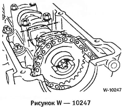
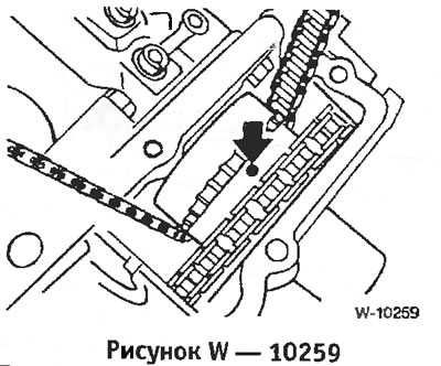
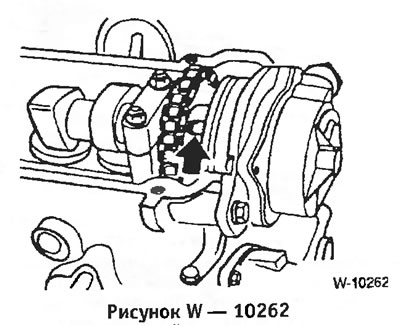
Caution: After removing the head, do not turn the camshaft and crankshaft, otherwise the open valves will rest against the pistons during installation. The figure shows the sprocket of the high-pressure fuel pump. The mark should be facing up.
Insert and tighten the cylinder head bolts by hand, lubricated with engine oil.
Caution: Tighten the cylinder head bolts very carefully. Before tightening the bolts, check the accuracy of the torque wrench. In addition, a protractor, such as the HAZET 6690, is required to tighten the cylinder head bolts. If you do not have a protractor, place the wrench on the bolt head, attach a square to the wrench handle and mark the desired angle with chalk. Then turn the wrench handle in one pass to the line marked with chalk.
Four-cylinder diesel engine:
Six-cylinder engine (Figure W 1097):
The cylinder head bolts are tightened in 6 passes. In each pass, tightening is performed in sequence from 1 to (Four-cylinder engine: 1 to 10)
- 1st pass: tightening with a torque wrench to 80 Nm.
- 2nd pass: tighten with a rigid wrench by 180° and then loosen the bolts.
- 3rd pass: tighten with a torque wrench to 50 Nm.
- 4th pass: tighten with a rigid wrench at 90°.
- 5th pass: tighten with a rigid wrench at 90°. After 25 minutes of engine operation (after its installation):
- 6th pass: tighten with a rigid wrench at 90°.
Replace the sealing gasket on the high-pressure fuel pump. Apply an elastic sealing compound, such as "3 Bond 1209".
Install the gearbox cover and tighten the bolts to a torque of 10 Nm.
Tighten the fasteners near the injector and also put the return fuel hose on the injector (Figure W 10254).
Screw in the 2 tension bar and chain guide retaining pins with new O-rings.
Screw the sprocket with the chain attached to the camshaft; do not tighten the bolt yet.
Caution: Contact surfaces must be degreased and clean.
Remove the locking pin from the chain tensioner so that the chain is taut. Screw the plug into the hole in the cylinder head.
Only if the camshaft is locked using the BMW adjustment template: The template is designed for adjusting chains with a mileage of up to approximately 20,000 km. For chains with higher mileage, a shim (feeler gauge) with a thickness of A = 4.61 mm should be installed on the intake side of the cylinder head. If the template is not used, turn the camshaft approximately 2 to the left and hold it in this position by the 27 mm Allen key.
In this position, tighten the camshaft sprocket in 2 passes:
- 1st pass: with a torque wrench to a tightening torque of 20 Nm;
- 2nd pass: tighten with a rigid wrench at 35°.
Caution: Remove the flywheel and crankshaft locking devices and the camshaft. Crank the engine by hand several times and check the valve timing again.
Insert the vacuum pump into the place with the O-ring, the rod should engage with the cutout in the camshaft sprocket.
Caution: The Torx head bolt on the camshaft sprocket has a hole for lubricating the vacuum pump. Clean the hole of any dirt.
Tighten the 2 vacuum pump bolts to 20 Nm. Either replace the inner bolt with a new one or coat it with a regular liquid sealant.
Insert the shock absorber and V-belt tensioner bracket and tighten.
Install the V-belt.
Check the integrity of the cylinder head cover gasket and replace if necessary.
Install the cylinder head cover and tighten the bolts crosswise from the inside out to a torque of 15 Nm. Ensure that the gasket is correctly positioned in the cutouts, see figure.
Six-cylinder engine: Bolt the front muffler pipe with a new gasket and new self-locking nuts to the turbocharger. Pre-coated the bolts with copper (high temperature) paste. First tighten all the bolts to a tightening torque of 30 Nm, and then tighten them to a torque of 50 Nm. In the version with pressure springs, tighten the nuts to a spring length of 27 mm.
Four-cylinder engine: Bolt the turbocharger with a new gasket and new self-locking nuts to the front muffler pipe. Pre-coated the bolts with copper (high temperature) paste. Tighten all bolts to a tightening torque of 45 Nm
Connect the wires to the glow plugs. Push the connectors until they snap into place.
Insert the injection tubes without bending them. Tighten the union nuts with a special wrench to a torque of 20 Nm.
Replace the intake manifold gaskets. Then install the intake manifold, tighten the bolts crosswise to 25 Nm.
Tighten the intake manifold support mounting bolts.
Route all hoses through the intake manifold mount and connect them.
Connect the electrical wires.
Connect the ground wire to the battery.
Fill with coolant.
Check the engine oil level, top up if necessary. If the cylinder head was removed to replace a blown cylinder head gasket, it is recommended to change the oil and replace the oil filter, as coolant may have gotten into the oil.
Caution: Warm up the engine for 25 minutes, remove the cylinder head cover and tighten the cylinder head bolts according to the instructions above.
Install the cylinder head cover and tighten the bolts crosswise in sequence from inside to outside to a torque of 15 Nm.
[Information taken from this resource BMWMAN.ru]
This article is available at russian, bulgarian, belarusian, ukrainian, serbian, croatian, romanian, polish, slovak, hungarian
Article verified: Chebotarev Vladislav
Share information:
Previous articles
БМВ E36: Engine repair
Next articles
Removal and installation the cylinder head. Models 320i, 325i, 328i…
Removal and installation the cylinder head. Models 318is, 318ti
Features of the 316i, 318i models produced since September 1993 (M43…
Removal and installation the cylinder head. Models 316i, 318i
Removal and installation the timing belt
Removal and installation the cylinder head. Models 318is, 318ti
Features of the 316i, 318i models produced since September 1993 (M43…
Removal and installation the cylinder head. Models 316i, 318i
Removal and installation the timing belt
Similar articles on other types of BMW cars:
Removal and installation the cylinder head — M50 engine (models 520i,… BMW 5 Series E34 (1988-1996)
Removal and installation the cylinder head — 520d models only (M47… BMW 5 Series E39 (1995-2003)
Cylinder head of the M70 series gasoline engine — removal and… BMW 7 Series E32 (1986-1994)
Removal and installation cylinder head covers BMW 7 Series E38 (1994-2001)
Removal and installation the cylinder head BMW X3 E83 (2003-2010)
Removal and installation the engine BMW X5 E53 (1999-2006)
Link in different formats to this page
Visitor comments
No comments yet
- General information
- Manual
- Maintenance
- Power unit
- Engine repair
- Cooling system
- Power system (gasoline)
- Injection system (gasoline)
- Fuel system (diesel)
- Exhaust system
- Ignition system
- Charge and launch systems
- Transmission
- Car gearbox
- Clutch and drive shafts
- Chassis
- Brake system
- Suspension front and rear
- Steering
- Body
- Body care and repair
- Exterior
- Interior
- Electrical equipment
- Troubleshooting
- Lighting and signaling
- Equipment and devices
- Heater and air conditioner
- Electrical circuits
- General information
- Manual
- Repair on the road
- Weekly checks
- Maintenance
- Troubleshooting
- Power unit
- 4 cylinder engines
- 6 cylinder engines
- Engine overhaul
- Cooling and heating
- Fuel and exhaust system
- Starting and charging system
- Ignition system
- Transmission
- Clutch
- Mechanical gearbox
- Automatic gearbox
- Cardan and drive shafts
- Chassis
- Brake system
- Wheel suspension
- Steering
- Body
- Exterior
- Interior
- Electrical equipment
- Equipment and devices
- Electrical circuits
- General information
- Maintenance
- Power unit
- Engine repair
- Cooling system
- Ignition system
- Supply system
- Fuel injection system
- Exhaust system
- Transmission
- Clutch
- Car gearbox
- Front and rear axle
- Chassis
- Steering
- Brake system
- Body
- Exterior
- Interior
- Electrical equipment
- Heating system
- Equipment and devices
- Power devices
- Electrical circuits
- Power unit
- M10/M20 engine
- M40 engine
- Ignition system
- Lubrication system
- Cooling system
- Supply system
- Fuel injection
- Exhaust system
- Transmission
- Clutch
- Manual gearbox
- Front axle
- Rear axle
- Chassis
- Steering
- Brake system
- Body
- Exterior
- Interior
- Electrical equipment
- Heating system
- Equipment and devices
- Electrical circuits
- General information
- Specifications
- Operation and maintenance
- 4-cylinder engine
- Engine repair
- Cooling and lubrication system
- Supply system
- Ignition system
- 6-cylinder engine
- Engine repair
- Cooling and lubrication system
- Supply system
- Fuel injection system
- Ignition system
- Transmission
- Clutch
- 4-speed manual gearbox
- 5-speed manual gearbox
- Automatic gearbox
- Cardan and rear axle
- Chassis
- Steering
- Front suspension
- Rear suspension
- Brake system
- Electrical equipment
- Equipment and devices
- Electrical circuits