
Table of contents: Removal ↓ Installation ↓
- Home
- BMW 5 Series
- E39
- Power unit
- Engine repair
- Removal and installation the cylinder head — model 525tds
Removal and installation the cylinder head — model 525tds (BMW 5 Series E39)
Note: This describes the removal and installation of the M51S engine head (model 525tds) Instructions for the M47 engine model 520d are given at the end of the chapter.
The defect of the cylinder head gasket is determined by one or more signs.
Removal
Disconnect the negative (-) battery cable. The battery is located in the luggage compartment behind the right side trim.
Caution: This will erase the contents of memory devices, such as the engine fault code memory device. Follow the instructions in the pave "Removal and installation the battery".
Drain into a container and save the coolant.
Loosen the clamp and disconnect the coolant hose coming from the radiator from the thermostat housing.
Drain the coolant from the engine by unscrewing the drain plug on the side of the cylinder block under the exhaust manifold. After draining, immediately screw the plug back in place and tighten.
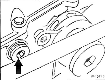
Unscrew the fastening (left hand thread) and remove the fan with viscous coupling.
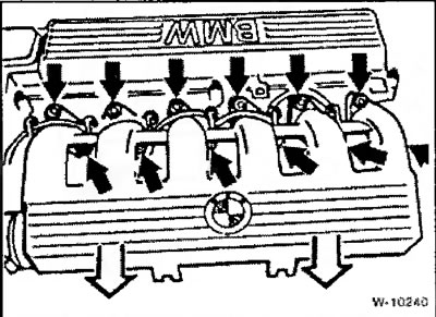
Remove the engine covers at the intake manifold.
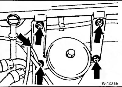
Loosen the intake manifold holders and remove them.
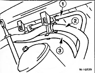
Disconnect the following hoses from the holder on the cylinder head:
- 1 - brake booster vacuum hose,
- 2 - coolant hose for heater,
- 3 - fuel line to the high-pressure fuel pump (HPFP).
Remove the vacuum hose at the intake port (at the exhaust gas recirculation valve).
Press down on the wire retainer and disconnect the electrical connector from the intake manifold temperature sensor.
Loosen the exhaust gas recirculation system pipe fastening to the intake manifold.
Loosen the clamp and disconnect the air supply hose from the intake manifold.
Loosen the intake manifold mount.
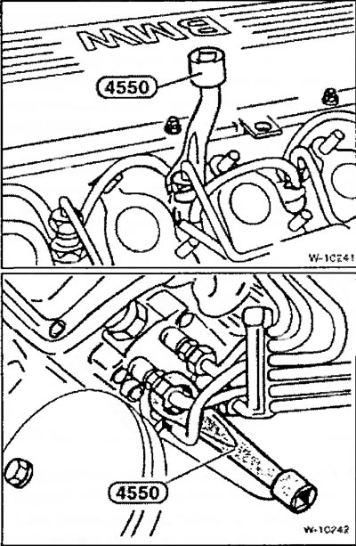
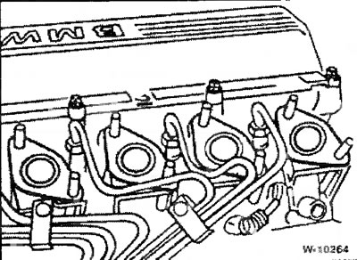
Unscrew the union nuts of the high-pressure fuel lines at the injectors and the high-pressure fuel pump. To do this, you will need a special key from BMW or HAZET4550. Close all openings on the fuel lines, injectors and high-pressure fuel pump with protective caps.
Release the connector contacts and remove the glow plug tips.
Disconnect the injector needle lift sensor plug connector.
Loosen the fastening of the exhaust gas recirculation system pipeline to the exhaust manifold and the holder and remove the pipeline.
Remove the poly V-belt.
Loosen the turbocharger mount to the exhaust manifold.
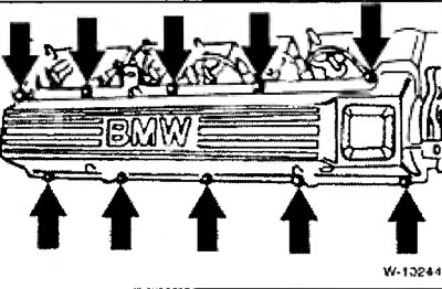
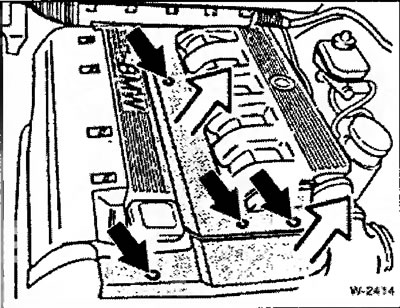
Loosen all cylinder head cover mounting bolts uniformly, first by ½ turn, and then completely adjust. Remove the cylinder head cover.
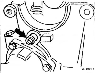
Loosen the fastening of the hydraulic V-belt tensioner and remove the damper.
Attention: Store the removed tensioner only in the installation position, i.e. vertically, otherwise malfunctions may occur in its operation later.
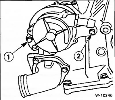
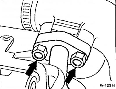
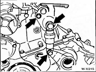
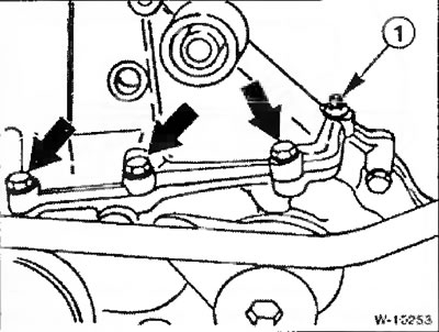
Unscrew bolts "1" and "2" and remove the vacuum pump. Bolt "2" is also a support for the guide bar of the camshaft drive chain. Since the thread under the bolt must be sealed, a new bolt should be screwed in. After each loosening, the bolt must either be replaced with a new one or lubricated with a regular liquid sealant before screwing in.
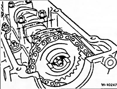
Place the engine crankshaft in a position where the piston of cylinder 1 is at TDC, with the tops of the camshafts of the intake and exhaust camshafts for cylinder 1 (from the camshaft drive chain side) must be equally directed upwards. The arrows on the sprockets of both camshafts must be directed upwards. The crankshaft can be turned in different ways:
- engage 5th gear and roll the car forward on a level surface or
- turn the crankshaft belt pulley with a socket wrench by the central mounting bolt in the direction of rotation (with neutral gear engaged).
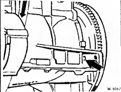
Fix the engine crankshaft in this position using the BMW 11 2 300 device or another suitable pin. To do this, insert the pin through the hole in the cylinder block into the hole in the flywheel. If available, first remove the plug from the hole in the cylinder block.
Caution: Do not turn the crankshaft or camshaft again after removing the cylinder head.
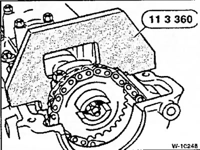
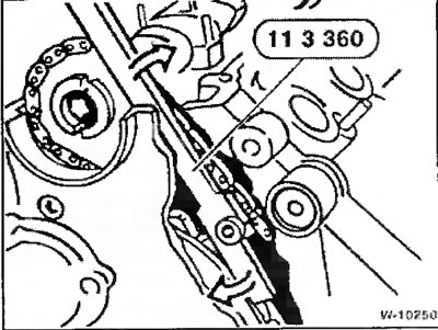
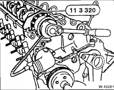
Lock the camshaft with a BMW device. The device is not absolutely necessary, since when releasing the sprocket fastening, you can hold the camshaft by the Allen key SW 27.
Place a suitable lever against the chain tensioner bar and press it down.
Unscrew the plug and secure the tensioner in the pressed position using a suitable pin.
Holding the camshaft by the Allen key with a SW 27 key, unscrew the fastening and remove the camshaft sprocket. Prevent the chain from slipping down with a wire hook.
Unscrew the tensioner bar support pin from the cylinder head and remove it together with the sealing ring.
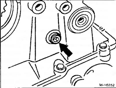
Unscrew the guide bar support pin and remove it together with the sealing ring.
Loosen the fastening of the sprocket niche cover. Fastening "1" is made in the form of a stud with a nut.
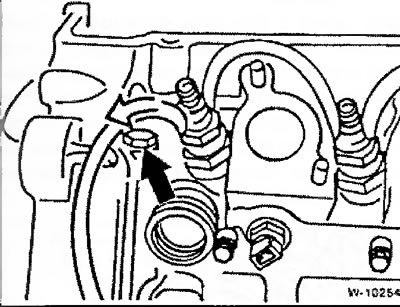
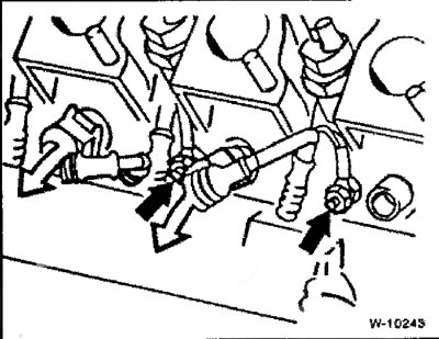
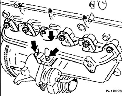
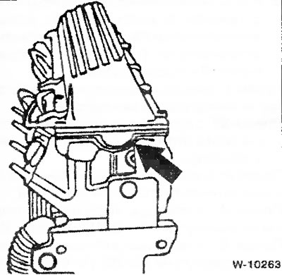
Loosen the "arrow" bolt and remove the hose from the injector to drain leaking fuel.
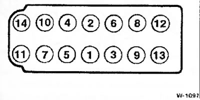
Loosen the cylinder head mounting bolts by ½ turn in the sequence from 14 to 1. Then unscrew the bolts in the same sequence. To unscrew the bolts, you need a replacement head size E12 for bolts with external splines.
Remove the cylinder head.
Caution: The cylinder head must not be placed directly on the workbench with the sealing surface, as this may damage the fully open valves. Therefore, the cylinder head should be placed on 2 wooden supports.
Installation
Before installation, clean the cylinder head and cylinder block from sealant residues with a suitable scraper. Make sure that sealant residues do not get into the holes, for which purpose cover the holes with rags.
Check the cylinder head and cylinder block for straightness in the longitudinal and transverse directions using a steel ruler.
Note: Finishing of the cylinder head is not allowed. If there is any unevenness, replace the cylinder head.
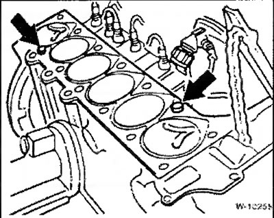
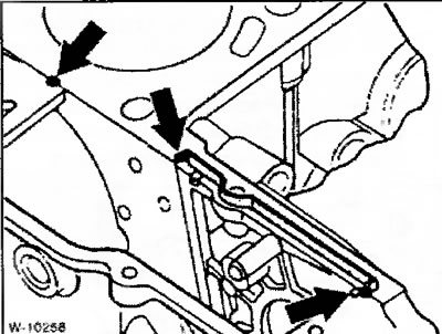
Check the correct fit of the guide bushings "arrows". The bushings serve to center the sealing gasket and the cylinder head.
Check for oil or other deposits in the cylinder block holes under the cylinder head bolts - if there is, remove it. If there is no compressed air available, wrap a screwdriver in a rag and wipe the holes thoroughly.
Caution: There must be no oil in the blind holes, otherwise the bolts will not be able to tighten the cylinder head to the required force, although they will be tightened to the prescribed torque value. In addition, the cylinder block may crack in this case.
Always replace the sealing gasket and cylinder head mounting bolts with new ones.
Place the new cylinder head gasket dry and on a dry surface so that the holes in the head and cylinder block are not covered. Depending on the thickness, the gasket is marked with a different number of holes. The new gasket must be the same thickness (with the same number of holes), that and the removed gasket.
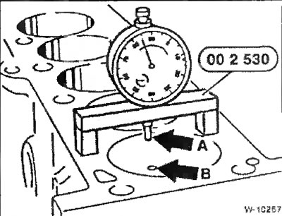
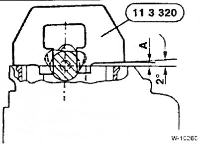
If it is not clear what thickness the new gasket should be, for example, after repairing the engine cylinder block, it is necessary to measure the protrusion of the pistons from the cylinder block using a linear displacement indicator. The thickness of the sealing gasket is selected in accordance with the maximum protrusion of the pistons of all six cylinders. To measure, install the indicator at point "A" and slightly turn the crankshaft clockwise and counterclockwise to determine the greatest protrusion of the piston from the cylinder block. Repeat the measurement at point "B". The average value determined from the results of measurements at points "A" and B- is taken as the piston protrusion. Perform similar measurements of the piston protrusion of the remaining cylinders.
Based on the obtained values, the average value of piston protrusion is determined. To do this, the obtained values are added up and the sum is divided by B. If the average value of piston protrusion is less than 0.76 mm, it is necessary to use a sealing gasket with two marking holes. If the protrusion is 0.76 mm or more, a sealing gasket with three holes is installed.
Caution: If one or more cylinders have a piston protrusion greater than 0.81 mm, a three-hole seal must be used in any case.
Only for version with injection pump bracket: replace the shaped rubber seal. Clean the groove for the seal. Seal the ends of the groove with Drei Bond 1209 sealant.
Seal the gaps in the joints between the sprocket housing cover and the cylinder head with Drei Bond 1209 sealant.
With the help of an assistant, place the cylinder head on the cylinder block, making sure it is not tilted, otherwise the seal will be damaged.
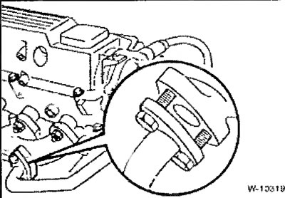
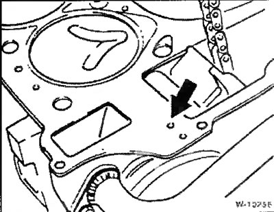
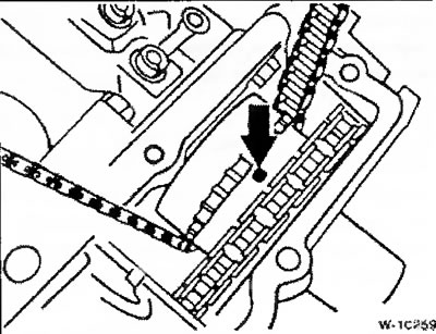
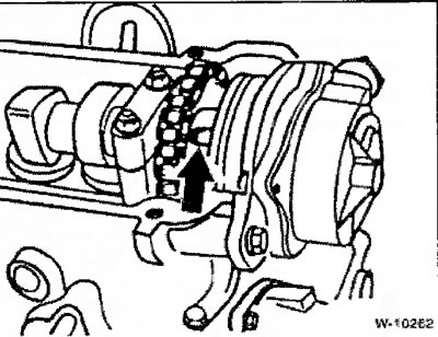
Caution: The camshaft and crankshaft must not be turned after the cylinder head has been removed, as the open valves will rest against the piston. If the shafts have been turned, they must be set in the correct position before installing the cylinder head, see "Removal". The figure shows the sprocket of the high-pressure fuel pump drive of a diesel engine. The mark on the sprocket must be facing upwards.
New cylinder head mounting bolts can be easily lubricated with engine oil and tightened by hand.
Caution: The cylinder head bolts must be tightened very carefully. The torque wrench must be checked for accuracy before tightening. In addition, a protractor, such as the HAZET 6690, is required to tighten the cylinder head bolts. Alternatively, the torque wrench is placed on the bolt head so that the handle of the wrench is positioned along the cylinder head, a 90° angle is measured with a protractor and a mark is made on the cylinder head with chalk.
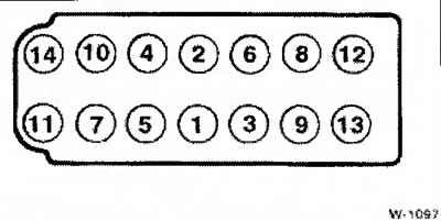
New cylinder head bolts are tightened in 6 stages. In each stage, the bolts are tightened in sequence from 1 to 14.
- Step 1: Using a torque wrench, tighten the bolts to a torque of BO Nm.
- Step 2: Using the locked key, loosen the bolts again by 180° (½ turn).
- Step 3: Using a torque wrench, tighten the bolts to 50 Nm.
- Step 4: Using the locked key, turn it an additional 90° (¼ turn).
- Step 5: Using the locked key, turn it an additional 90° (¼ turn).
- After warming up the engine for 25 minutes (after the engine assembly is complete): Step 6: Using the locked key, turn it further by 90°.
Place the sprocket niche cover on and tighten the mounting bolts to a torque of 10 Nm.
Tighten the fastener near the injector and put the hose on the injector to drain the leaking fuel, see figure W-10254 above.
Screw in 2 support pins with new sealing rings for the tensioner and guide film.
Screw the sprocket with the chain attached to the camshaft, do not tighten the mounting bolt too much.
Attention: The contact surfaces of the mating parts must be free of grease and clean.
Remove the chain tensioner locking pin and thereby create chain tension. Screw the plug into the cylinder head into the hole for the locking pin.
Only for cases where the camshaft is fixed using a BMW timing gauge: The gauge is designed for adjusting chains with a mileage of up to approximately 20,000 km.
For chains with higher mileage, it is necessary to install a gasket on the intake side of the cylinder head (calibrated plate) thickness A = 4.5 mm. If the gauge is not used, turn the camshaft 2° to the left and hold it in this position by the Allen key SW 27.
In this position, tighten the camshaft sprocket in 2 steps:
- Step 1: Using a torque wrench, tighten the bolt to 20 Nm.
- Step 2: Using the locked key, turn it to an angle of 35°.
Caution: Remove the crankshaft locking pin from the flywheel hole and the camshaft locking tool. Turn the engine crankshaft several times by hand and check the valve timing.
Insert the vacuum pump with a new sealing ring so that the pump arm fits into the recess in the sprocket on the camshaft.
Caution: The sprocket mounting bolt has a hole for supplying grease to the vacuum pump. Clean the hole from dirt.
Tighten the 2 vacuum pump mounting bolts to 20 Nm. Either replace the internal bolt with a used one or lubricate it with liquid sealant before tightening to ensure the threaded connection is tight.
Attach the damper and the V-belt tensioner bracket and screw them on.
Install the poly V-belt.
Check the cylinder head cover gasket for damage; replace the gasket if necessary.
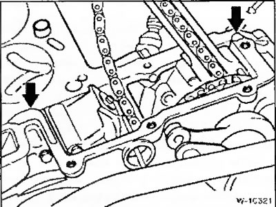
Place the cylinder head cover and tighten the mounting bolts crosswise in the sequence "from the inside to the outside" with a torque of 15 Nm. Before tightening the bolts, pay attention to the incorrect position of the sealing gasket in the recess of the cylinder head, see the figure.
Screw the turbocharger with a new sealing gasket to the exhaust manifold with new self-locking nuts. Pre-lubricate the bolts with high-temperature grease. Tighten all bolts to a torque of 45 Nm.
Connect the glow plug connectors.
Connect the plug to the injector needle lift sensor connector.
Attach the high-pressure fuel lines, do not bend the fuel lines. Tighten the union nuts on the injector and fuel injection pump fittings with a special wrench to a torque of 20 Nm.
Replace the intake manifold seals. Then attach the manifold and tighten the fastening crosswise to 25 Nm.
Tighten the intake manifold mount bolts.
Route all hoses in the intake manifold holder and connect them, see "Removal".
Tighten the EGR pipe to the exhaust manifold, screw on the bracket and the intake pipe.
Connect the electrical wires.
Connect the battery ground wire, set the clock, tune the radio to the transmitting radio stations.
Connect the coolant hose from the radiator to the thermostat housing and secure the hose with a clamp.
Fill with coolant.
Screw it on viscous coupling fan (left hand thread).
Check the engine oil level, top up if necessary. If the cylinder head was removed due to a defective sealing gasket, it is recommended to replace the oil and oil filter, as the engine oil may contain coolant.
Caution: Warm up the engine for 25 minutes. Remove the cylinder head cover and, with the key locked, tighten the cylinder head bolts 90° in the tightening direction in the sequence shown above in Fig. W-1097.
To precisely tighten the cylinder head bolts, a protractor is required, such as the HAZET 6690. Alternatively, a torque wrench is placed on the bolt head so that the wrench handle is positioned along the cylinder head, a 90° angle is measured with a protractor, and a mark is made on the cylinder head with chalk.
Attach the cylinder head cover and tighten the mounting bolts in a crosswise manner in the sequence "from the inside to the outside" to a torque of 15 Nm.
Install the engine cover.
The original article is available on the website: «bmwman.ru»
This article is available at russian, bulgarian, belarusian, ukrainian, serbian, croatian, romanian, polish, slovak, hungarian
Article verified: Ilyinsky Matvey
Share information:
Previous articles
БМВ E39: Engine repair
Next articles
Similar articles on other types of BMW cars:
Removal and installation the cylinder head BMW 3 Series E30 (1982-1994)
Removal and installation the cylinder head. Models 318is, 318ti BMW 3 Series E36 (1990-2000)
Cylinder head of gasoline engines of the M52 series — removal and… BMW 7 Series E32 (1986-1994)
Removal and installation cylinder head covers BMW 7 Series E38 (1994-2001)
Removal and installation the cylinder head BMW X3 E83 (2003-2010)
Removal and installation the lock cylinder BMW X5 E53 (1999-2006)
Link in different formats to this page
Visitor comments
No comments yet
- General information
- Governing bodies
- Manual
- Maintenance
- Power unit
- Engine repair
- Lubrication system
- Cooling system
- Ignition system
- Supply system
- Injection system (gasoline)
- Injection system (diesel)
- Exhaust system
- Transmission
- Clutch
- Car gearbox
- Front axle
- Rear axle
- Chassis
- Steering
- Brake system
- Wheels and tires
- Body
- Interior
- Exterior
- Heating system
- Electrical equipment
- Equipment and devices
- Power devices
- Windscreen wipers
- Electrical circuits
- General information
- Manual
- Maintenance
- Power unit
- Engine repair
- Ignition system
- Engine lubrication system
- Cooling system
- Fuel system (gasoline)
- Fuel system (diesel)
- Exhaust system
- Transmission
- Clutch
- Car gearbox
- Chassis
- Front and rear suspension
- Steering
- Brake system
- Body
- Exterior
- Interior
- Electrical equipment
- Heating system
- Equipment and devices
- Power devices
- Electrical circuits
- General information
- Manual
- Maintenance
- Power unit
- Engine in a car
- Engine overhaul
- Cooling system
- Supply system
- Ignition system
- Control system
- Transmission
- Clutch
- Manual gearbox
- Automatic gearbox
- Transmission line
- Chassis
- Steering
- Front suspension
- Rear suspension
- Brake system
- Body
- Body elements
- Car care and painting
- Electrical equipment
- Heater and air conditioner
- Equipment and devices
- Starter and generator
- Electrical circuits
- General information
- Operation and maintenance
- Specifications
- Power unit
- Engine repair
- Cooling and lubrication system
- Supply system
- Ecotronic power supply system
- Fuel injection system
- Ignition system
- Transmission
- Clutch
- Gearbox BMW 242/4
- Gearbox Getrag 262/8
- Gearbox Getrag 265/6
- Automatic gearbox
- Cardan gear
- Rear axle
- Chassis
- Steering
- Front suspension
- Rear suspension
- Brake system
- Electrical equipment
- Equipment and devices
- Electrical circuits