
Table of contents: Removal ↓ Installation ↓
- Home
- BMW 5 Series
- E39
- Power unit
- Engine repair
- Removal and installation the camshaft — 6-cylinder petrol engine
Removal and installation the camshaft — 6-cylinder petrol engine (BMW 5 Series E39)
Since special BMW tools are required to perform the work, it is recommended that this work be performed at a BMW service station. Below is a description of how to remove the camshafts with the cylinder head removed. This also applies to the installed cylinder head, but in this case, preliminary work must be performed before loosening the bolts securing it in accordance with the instructions in the chapter "Removing and installing the cylinder head".
If necessary, measure the clearances before removing the camshaft. The prescribed value of the axial clearance (free movement in the direction of the shaft axis): 0.15-0.33 mm; radial clearance (free movement in the direction perpendicular to the shaft axis) — 0.02-0.054 mm.
Remove the cylinder head.
Unscrew the studs.

Remove the spark plugs.
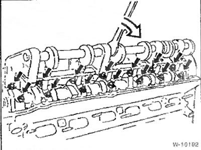
Install the device and, using the threaded holes of the spark plugs of cylinders 1 and 4, tighten the device fastening to a torque of 25 Nm.
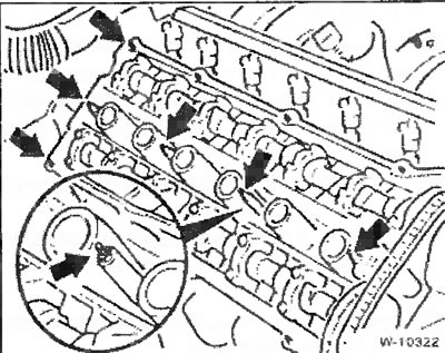
Press the bearing caps by turning the eccentric shaft of the device.
Loosen all bearing caps.
Loosen the device and remove it.
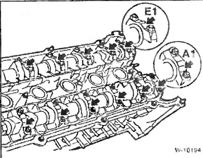
Remove the bearing caps and camshaft. Place the removed caps according to their numbers; when reassembling, they must be reinstalled in their original locations. The bearing caps of the exhaust camshaft are marked with marks from A1 to A7, and the bearing caps of the inlet camshaft are marked with marks from E1 to E7.
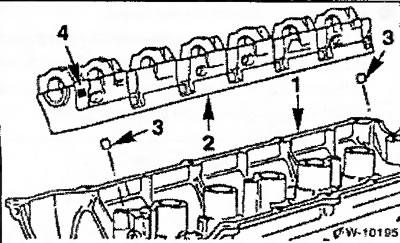
If required, for example, when it is necessary to remove the valves, then dismantle the bearing bed block "2" complete with the valve tappets from the cylinder head "1". Pay attention to the centering bushings "3". In the position indicated by the arrow "4", the bearing bed of the exhaust camshaft has the mark "A", and the bearing bed of the inlet shaft has the mark "E".
If the camshaft was removed from the removed cylinder head, turn the engine crankshaft approximately 30° past TDC in the direction of its rotation (to the right, by the hexagon on the belt pulley). This will prevent any pistons from being at TDC and the valves from touching the pistons. Install the camshaft timing chain and wait the time specified above. Only then return the crankshaft to TDC and install the camshaft drive chain, see the chapter "Removing and installing the cylinder head".
Check the valve lifters for wear and scratches; replace if necessary.
Lubricate the camshaft bearings with engine oil and insert the camshafts so that the tops of the cams for the intake and exhaust valves of the first cylinder are facing each other.
Place the bearing bed block with the tappets installed on the cylinder head. Make sure that the centering bushings "3" are present, see Figure W-10195.
Install the bearing caps in accordance with the existing markings. The caps should not be installed in the same places where they were before removal.
Install the fixture and tighten the bearing caps.
Tighten the camshaft bearing caps to 15 Nm.
Loosen and remove the device, screw in the spark plugs.
Install the cylinder head.
[The original article is available on the website: «www.bmwman.ru»]
If necessary, measure the clearances before removing the camshaft. The prescribed value of the axial clearance (free movement in the direction of the shaft axis): 0.15-0.33 mm; radial clearance (free movement in the direction perpendicular to the shaft axis) — 0.02-0.054 mm.
Removal
Remove the cylinder head.
Unscrew the studs.
Note: To remove the camshafts, you need the BMW 11 3 260 tool. The tool is designed to hold the camshaft bearings in the mounting position when releasing the fastening of their caps. The working operations are the same for both camshafts, the sequence of operations during removal is arbitrary.
Remove the spark plugs.
Install the device and, using the threaded holes of the spark plugs of cylinders 1 and 4, tighten the device fastening to a torque of 25 Nm.
Press the bearing caps by turning the eccentric shaft of the device.
Loosen all bearing caps.
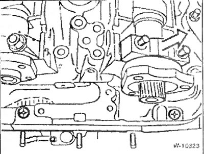
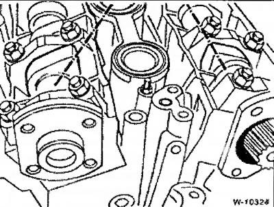
Note: Cover 1 of the intake camshaft is centered by a guide sleeve. To avoid camshaft distortion, unscrew the cover fastening and remove the cover.
Loosen the device and remove it.
Remove the bearing caps and camshaft. Place the removed caps according to their numbers; when reassembling, they must be reinstalled in their original locations. The bearing caps of the exhaust camshaft are marked with marks from A1 to A7, and the bearing caps of the inlet camshaft are marked with marks from E1 to E7.
If required, for example, when it is necessary to remove the valves, then dismantle the bearing bed block "2" complete with the valve tappets from the cylinder head "1". Pay attention to the centering bushings "3". In the position indicated by the arrow "4", the bearing bed of the exhaust camshaft has the mark "A", and the bearing bed of the inlet shaft has the mark "E".
Caution: If no action is taken, the valve tappets will slip down from the bearing block. The BMW car repair shop uses suction cups that are placed on the tappets from above and prevent them from slipping out of the bearing block. Mark the tappets. If the tappets were removed from the block, they must be installed in their original places.
Caution: Removed valve lifters must not be kept upside down for more than 10 minutes, as this will cause the engine oil to leak out of them, albeit slowly, and the automatic valve clearance compensation will stop.
Installation
Caution: If the camshaft has been removed, the following must be observed. The hydraulic valves expand without load from the camshaft and require some time to contract again after installation. Therefore, the valves may open for a longer time than determined by the valve timing adjustment and collide with the piston. Therefore, it is necessary to ensure that a certain time is maintained between installation of the camshaft and installation of the cylinder head: at +20°C (room temperature) — 4 minutes, at +10°C — 11 minutes. After installing the cylinder head, wait another 30 minutes before turning the engine crankshaft.
If the camshaft was removed from the removed cylinder head, turn the engine crankshaft approximately 30° past TDC in the direction of its rotation (to the right, by the hexagon on the belt pulley). This will prevent any pistons from being at TDC and the valves from touching the pistons. Install the camshaft timing chain and wait the time specified above. Only then return the crankshaft to TDC and install the camshaft drive chain, see the chapter "Removing and installing the cylinder head".
Check the valve lifters for wear and scratches; replace if necessary.
Lubricate the camshaft bearings with engine oil and insert the camshafts so that the tops of the cams for the intake and exhaust valves of the first cylinder are facing each other.
Place the bearing bed block with the tappets installed on the cylinder head. Make sure that the centering bushings "3" are present, see Figure W-10195.
Install the bearing caps in accordance with the existing markings. The caps should not be installed in the same places where they were before removal.
Install the fixture and tighten the bearing caps.
Tighten the camshaft bearing caps to 15 Nm.
Loosen and remove the device, screw in the spark plugs.
Install the cylinder head.
[The original article is available on the website: «www.bmwman.ru»]
This article is available at russian, bulgarian, belarusian, ukrainian, serbian, croatian, romanian, polish, slovak, hungarian
Article verified: Ilyinsky Matvey
Share information:
Previous articles
БМВ E39: Engine repair
Next articles
Removal and installation the cylinder head — 520d models only (M47…
Removal and installation the cylinder head — model 525tds
Removal and installation the cylinder head (only M52TU engine…
Removal and installation the cylinder head / replacing the cylinder…
Removal and installation the intake manifold
Removal and installation the cylinder head — model 525tds
Removal and installation the cylinder head (only M52TU engine…
Removal and installation the cylinder head / replacing the cylinder…
Removal and installation the intake manifold
Similar articles on other types of BMW cars:
Removal and installation the cylinder head. Models 318tds/325td… BMW 3 Series E36 (1990-2000)
Camshaft timing chain housing (M43TU engine) — removal and… BMW 3 Series E46 (1998-2006, petrol)
Cylinder head cover for M52 series petrol engines — removal and… BMW 7 Series E32 (1986-1994)
Removal and installation cylinder head covers BMW 7 Series E38 (1994-2001)
Removal and installation the engine assembly BMW X3 E83 (2003-2010)
Removal and installation the engine BMW X5 E53 (1999-2006)
Link in different formats to this page
Visitor comments
No comments yet
- General information
- Governing bodies
- Manual
- Maintenance
- Power unit
- Engine repair
- Lubrication system
- Cooling system
- Ignition system
- Supply system
- Injection system (gasoline)
- Injection system (diesel)
- Exhaust system
- Transmission
- Clutch
- Car gearbox
- Front axle
- Rear axle
- Chassis
- Steering
- Brake system
- Wheels and tires
- Body
- Interior
- Exterior
- Heating system
- Electrical equipment
- Equipment and devices
- Power devices
- Windscreen wipers
- Electrical circuits
- General information
- Manual
- Maintenance
- Power unit
- Engine repair
- Ignition system
- Engine lubrication system
- Cooling system
- Fuel system (gasoline)
- Fuel system (diesel)
- Exhaust system
- Transmission
- Clutch
- Car gearbox
- Chassis
- Front and rear suspension
- Steering
- Brake system
- Body
- Exterior
- Interior
- Electrical equipment
- Heating system
- Equipment and devices
- Power devices
- Electrical circuits
- General information
- Manual
- Maintenance
- Power unit
- Engine in a car
- Engine overhaul
- Cooling system
- Supply system
- Ignition system
- Control system
- Transmission
- Clutch
- Manual gearbox
- Automatic gearbox
- Transmission line
- Chassis
- Steering
- Front suspension
- Rear suspension
- Brake system
- Body
- Body elements
- Car care and painting
- Electrical equipment
- Heater and air conditioner
- Equipment and devices
- Starter and generator
- Electrical circuits
- General information
- Operation and maintenance
- Specifications
- Power unit
- Engine repair
- Cooling and lubrication system
- Supply system
- Ecotronic power supply system
- Fuel injection system
- Ignition system
- Transmission
- Clutch
- Gearbox BMW 242/4
- Gearbox Getrag 262/8
- Gearbox Getrag 265/6
- Automatic gearbox
- Cardan gear
- Rear axle
- Chassis
- Steering
- Front suspension
- Rear suspension
- Brake system
- Electrical equipment
- Equipment and devices
- Electrical circuits