
Attention:
- After unscrewing, aluminum bolts must be replaced.
- To ensure identification of aluminum bolts, the ends of their heads are painted blue.
- Strictly observe the tightening torque and angle (danger of damage).
1. Remove the cylinder head cover.
2. Remove the intake actuator.
3. Remove the intermediate lever.
4. Adjust the valve timing.
Note:
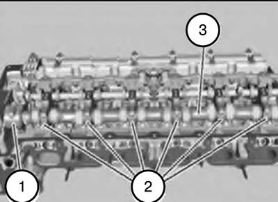
- All bearing caps (1 and 2) are numbered from 1 to 6.
- The bearing cover (1) serves as a thrust bearing.
5. Unscrew the bearing cap bolts 1 through 6 (1 and 2).
Tightening torque: 9 Nm.
6. Place all bearing caps in fixture 114481 in order.
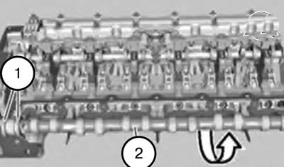
7. Remove the intake camshaft (2) by moving it upwards.
Note:
- When installing, it is necessary to clean all bearing beds and lightly lubricate them.
- Check the rectangular rings (1) for damage and replace if necessary.
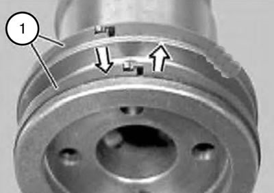
Note: Rectangular rings (1) snap into place at the joint.
8. Unclasp the rectangular ring (1), one end up, the other end down, and remove it forward.
Caution: Rectangular rings (1) are easily broken.
Attention:
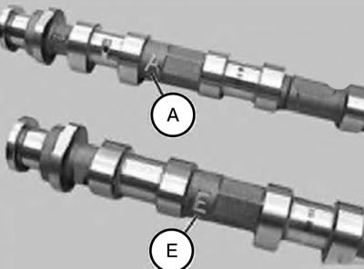
- The markings on the intake camshaft and the exhaust camshaft are different.
- Installing the intake camshaft in place of the exhaust camshaft and vice versa will damage the engine.
A - Exhaust camshaft.
E - Intake camshaft.
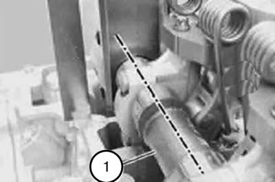
9. Insert the intake camshaft (1) so that the part number on the flat side points upwards.
10. Install the intake camshaft (1) so that the cams point upwards at an angle.
11. Place tool 114281 on the chamfers.
12. Assemble the engine.