
L-Jetronic systems are equipped with a separate idle speed control unit (computer), located under the dashboard. The idle air stabilization valve has an adjusting screw. Early models are equipped with plastic valves, however, they are also adjustable by disconnecting the hose and inserting a very thin screwdriver inside.
Early Motronic models are also equipped with a separate idle control unit (computer), located under the dashboard. The stabilization air valve has an adjusting screw.
On late Motronic systems, the stabilization air valve is controlled by the ECU and there is no adjustment.
Preliminary check
Before performing any checks on the idle air control valve, ensure that the following conditions are met:
- The engine must be at operating temperature (60°C)
- Electrical equipment must be turned off (air conditioner, heater, headlights, additional cooling fan and others)
- Throttle position sensor should work properly (see chapter Engine management and emission control systems)
- There must be no leaks in the exhaust system
- There must be no vacuum leaks
- Oxygen sensor, if installed, must be good (see chapter Engine management and emission control systems)
- Connect a tachometer in accordance with the manufacturer's instructions.
Switch off the ignition before making any electrical connections.
The idle speed control air valve operates continuously when the ignition is on. Start the engine and check that the valve vibrates and hums slightly.
L-Jetronic system
Examination
1. With the engine running, disconnect the electrical connector from the valve. The idle speed should increase to about 2000 rpm.
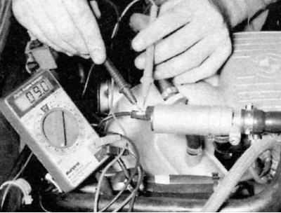
2. If the idle speed does not increase, stop the engine. Check the resistance between the valve contacts with an ohmmeter. At an ambient temperature of about 20°C, the resistance should be between 9 and 10 ohms.
3. Using two jumpers, apply battery voltage to the valve and check that the valve is tightly closed. When the voltage is removed, the valve should open.
4. If the idle air stabilization valve does not withstand at least one of the tests, then it should be replaced.
5. If the vacuum idle control valve passes the tests, check the control current.
6. Disconnect the electrical connector from the valve. Connect a jumper wire from one pin of the electrical connector to one of the valve pins. Connect an ammeter between the other pin of the electrical connector and the remaining valve pin (with a range of 0 to 1000 mA). Start the engine and let it idle. With the motor running, the current should be between 400 and 500 mA. If this value is not correct, adjust the valve (see point 1).
The idle regulator current varies between 400 and 1100 mA when the engine is too cold, if the coolant temperature sensor is faulty, if idle speed adjustment is required, if there is a vacuum leak in the engine, or if electrical accessories are turned on.
7. If there is no current, send the idle speed control unit to a BMW dealer or other specialist for diagnosis.
Idle stabilizer control unit (located under the dashboard) may malfunction due to an electrical connector that periodically turns the valve on and off. Check the connector carefully before replacing any parts. Sometimes a new control unit will only temporarily fix the problem.
Adjustment
1. With the ignition off, connect a tachometer in accordance with the manufacturer's instructions.
2. Make sure the ignition timing is set correctly (see chapter Ignition system).
3. Connect an ammeter to the valve (see point 6).
4. With the engine running, the current should be 450-470 mA at 850-900 rpm (manual transmission) or 460-480 mA at 850-900 rpm (automatic transmission).
5. If the control current is not correct, turn the adjusting screw until the current is correct.
On metal valves, the adjusting screw is mounted on the outside. On plastic valves, the adjusting screw is located inside and to access it it is necessary to disconnect the hose from the valve.
Motronic systems
Examination
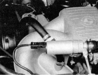
In this system, two types of idle speed stabilization air valves are used; early models are usually equipped with a two-way valve, while later models are equipped with three-way valves.
1. Disconnect the electrical connector from the valve while the engine is running. The idle speed should increase to 2000 rpm.
2. If the idle speed has not increased:
- 2-wire valve - Apply battery voltage to the valve with two jumpers and make sure that the valve closes tightly. When the voltage is removed, the valve should open. Also check valve resistance (see picture below). The resistance should be around 9-10 ohms.
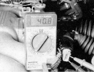
- Three way valve - Stop the engine and disconnect the electrical connector from the valve. Check the resistance between the two extreme contacts of the valve with an ohmmeter. It should be about 40 ohms.
3. Check the resistance between the central and outer contacts of the valve. They should be about 20 ohms.
4. If the idle air stabilization valve fails any of the checks, replace the valve.
5. If the idle air control valve passes all tests, then check the control current (two-way valve) or tension (three-way valve) in the following way.
6. For two-wire valves, connect an ohmmeter (with a range of 0 to 1000 mA), as described in point 6. Start the engine and let it idle. On a running engine, the current should be in the range of 400-500 mA. Adjust valve. if the indications do not meet the requirements.
The regulator current will vary from 400-1100 mA if the engine is very cold, if the coolant temperature sensor is faulty, if there is a vacuum leak in the engine, or if electrical accessories are turned on.
7. If there is no current, the idle control unit (under the dashboard) should be sent to a BMW dealer or other specialist for inspection.
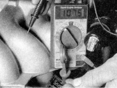
8. For three-wire valves, check the voltage at the electrical connector. With the ignition on, battery voltage must be present at the center terminal. Between the central and each of the extreme contacts there should be a voltage of about 10 V.
9. If there is no voltage, send the idle control unit (early models) or ECU (later models) to be checked by a BMW dealer or other specialist.
Adjustment (only early models)
1. With the ignition off, connect a tachometer in accordance with the manufacturer's instructions.
2. Make sure the ignition timing is set correctly (see chapter Ignition system).
3. Connect an ammeter to the valve as described in step 6.
4. With the engine running, the current should be 450-470 mA at 700-750 rpm.
5. If the current is not correct, turn the adjusting screw until it meets the requirement.
Turning the air valve screw clockwise increases the current, counterclockwise decreases the current.
Replacement
1. Disconnect from the air valve of stabilization of idling an electric socket and an arm. Remove the valve, disconnect the hoses.
2. Installation is reverse to removal.