
- Home
- BMW 5 Series
- E28
- Power unit
- Supply system
- Checking the operation, removing and installing the air flow meter
Checking the operation, removing and installing the air flow meter (BMW 5 Series E28)
Examination (l-Jetronic systems)
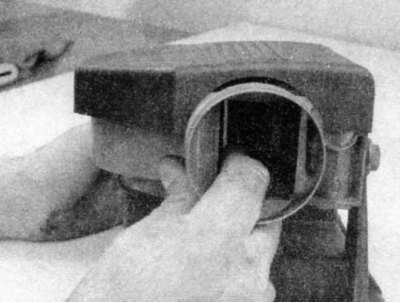
1. Disconnect the air flow meter from the inlet fitting. Carefully open and close the sensor flap and check for binding. The flap can bend during backfires, causing incorrect resistance measurements. The flap can bend and remain in a partially open position, causing rich mixture and stalling at idle.
2. Disconnect the electrical connector from the air flow meter.
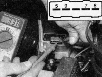
3. Check the resistance between contacts 7 and 8 with an ohmmeter. The resistance should increase steadily (without "flat spots") as the sensor flap is slowly moved from the fully closed position to the fully open position.
4. Also check the intake air temperature sensor (inside the flow meter). Check with an ohmmeter that the resistance between contacts 8 and 9 is correct (see the illustration above). The resistance at 20°C should be between 2200 and 2700 Ohms.
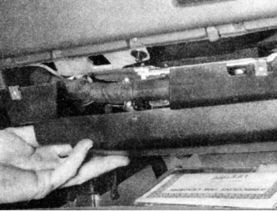
5. If the resistance values are correct, check the cables (see chapter On-board electrical equipment system). Connect the flow meter connector. Make sure the ignition is off. Disconnect the connector from the ECU (located under the dashboard on the right) and check the resistance between pins 7 and 8 with an ohmmeter. Carefully remove the cover from the flow meter and observe the change in resistance as it moves from the closed position to the fully open position. The test result should be the same as the previous test. If there are any differences in the results, there may be breaks or short circuits in the cable.
Functional check (motronic systems)
1. Make sure the ignition is off. Remove the ECU access cover (see chapter Engine management and emission control systems) and disconnect the cable connector.
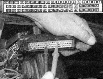
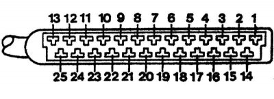
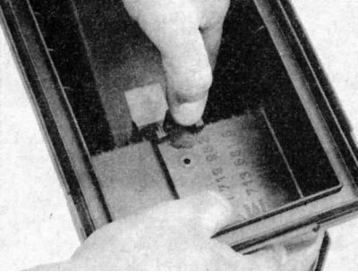
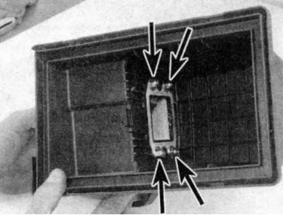
2. Check the resistance between the marked pins of the ECU electrical connector with an ohmmeter and check the resistance change when moving the paddle. On early Motronic systems use pins 7 and 9.

3. On later models - contacts 7 and 12.
4. The resistance should increase continuously (without "flat spots") as the sensor petal moves from the fully closed position to the fully open position.
Early Motronic systems feature a 35-pin electrical connector; later Motronic systems used a 55-pin connector.
5. If the resistance value is incorrect, check the cable.
Removal and installation (all systems)
1. Disconnect the electrical connector from the flow meter.
2. Remove the air cleaner (see section Removal and installation the air cleaner).
3. Loosen the nuts and remove the flow meter from the engine compartment or from the air cleaner.
4. Installation is the reverse of removal.
This article is available at russian, bulgarian, belarusian, ukrainian, serbian, croatian, romanian, polish, slovak, hungarian
Article verified: Zhuravleva Isolda
Share information:
Previous articles
БМВ E28: Supply system
Next articles
Checking the operation of the fuel injection system
Fuel injection systems
General information about fuel injection
Cleaning and adjusting the carburetor
Removal and installation the carburetor
Fuel injection systems
General information about fuel injection
Cleaning and adjusting the carburetor
Removal and installation the carburetor
Checking the operation, removing and installing the throttle body
Checking the operation and replacing the fuel pressure regulator
Checking the operation and replacing the cold start injector and…
Checking the operation and replacing fuel injectors
Checking the operation, adjusting and replacing the idle air…
Checking the operation and replacing the fuel pressure regulator
Checking the operation and replacing the cold start injector and…
Checking the operation and replacing fuel injectors
Checking the operation, adjusting and replacing the idle air…
Similar articles on other types of BMW cars:
Checking the air flow meter pressure disc BMW 3 Series E21 (1975-1983)
Checking, removing and installing the air damper regulator BMW 3 Series E30 (1982-1994)
Idle speed control valve — checking, removing and installing BMW 7 Series E32 (1986-1994)
Removal and installation the pipe between the air flow meter and the… BMW 7 Series E38 (1994-2001)
Checking the operation of the power steering pump BMW X3 E83 (2003-2010)
Checking the operation of the ECU-KSUD of the «DME» system BMW X5 E53 (1999-2006)
Link in different formats to this page
Visitor comments
No comments yet
- General information
- Governing bodies
- Manual
- Maintenance
- Power unit
- Engine repair
- Lubrication system
- Cooling system
- Ignition system
- Supply system
- Injection system (gasoline)
- Injection system (diesel)
- Exhaust system
- Transmission
- Clutch
- Car gearbox
- Front axle
- Rear axle
- Chassis
- Steering
- Brake system
- Wheels and tires
- Body
- Interior
- Exterior
- Heating system
- Electrical equipment
- Equipment and devices
- Power devices
- Windscreen wipers
- Electrical circuits
- General information
- Manual
- Maintenance
- Power unit
- Engine repair
- Ignition system
- Engine lubrication system
- Cooling system
- Fuel system (gasoline)
- Fuel system (diesel)
- Exhaust system
- Transmission
- Clutch
- Car gearbox
- Chassis
- Front and rear suspension
- Steering
- Brake system
- Body
- Exterior
- Interior
- Electrical equipment
- Heating system
- Equipment and devices
- Power devices
- Electrical circuits
- General information
- Manual
- Maintenance
- Power unit
- Engine in a car
- Engine overhaul
- Cooling system
- Supply system
- Ignition system
- Control system
- Transmission
- Clutch
- Manual gearbox
- Automatic gearbox
- Transmission line
- Chassis
- Steering
- Front suspension
- Rear suspension
- Brake system
- Body
- Body elements
- Car care and painting
- Electrical equipment
- Heater and air conditioner
- Equipment and devices
- Starter and generator
- Electrical circuits
- General information
- Operation and maintenance
- Specifications
- Power unit
- Engine repair
- Cooling and lubrication system
- Supply system
- Ecotronic power supply system
- Fuel injection system
- Ignition system
- Transmission
- Clutch
- Gearbox BMW 242/4
- Gearbox Getrag 262/8
- Gearbox Getrag 265/6
- Automatic gearbox
- Cardan gear
- Rear axle
- Chassis
- Steering
- Front suspension
- Rear suspension
- Brake system
- Electrical equipment
- Equipment and devices
- Electrical circuits