
Table of contents: Removal ↓ Installation ↓
- Home
- BMW 7 Series
- E32
- Power unit
- Minor engine repair
- Cylinder head of diesel engine series M51 — removal and installation
Cylinder head of diesel engine series M51 — removal and installation (BMW 7 Series E32)
Note: This chapter contains features that are unique to this series of engines. For general information on minor engine repairs, please refer to previous chapters.
Removal
Disconnect the ground wire.
Note: This will erase any fault information from the on-board computer battery.
Raise the car.
Unscrew the front muffler pipe from the exhaust manifold.
Remove the front muffler pipe from the turbocharger.
Drain the coolant from the engine.
Loosen the intake manifold mounting bolts and remove the mount.
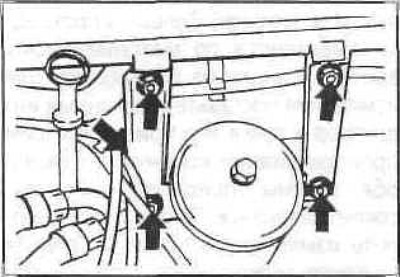
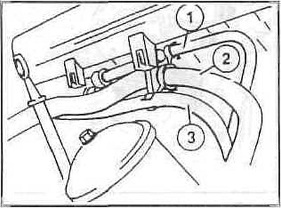
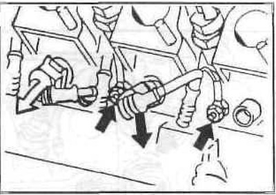
Remove the following hoses from the mounts on the cylinder head: brake booster vacuum hose (1), heater water hose (2), fuel hose to the high-pressure fuel pump (3).
Disconnect the vacuum hose from the intake manifold (on the exhaust gas recirculation valve).
Disconnect the intake manifold temperature sensor connector by pressing the wire clip.
Unscrew the intake manifold.
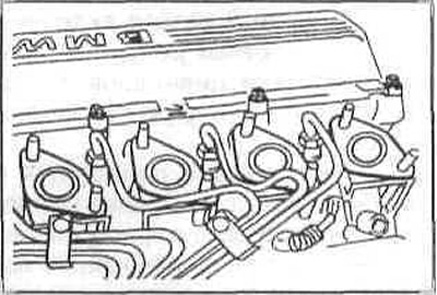
Unscrew the union nuts of the injection pipes on the injectors and on the high-pressure fuel pump. Close the holes with plugs.
Disconnect the cables from the glow plugs.
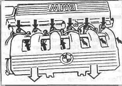
Remove the V-belt. Loosen the cylinder head cover mounting bolts first by ½ turn, then completely.
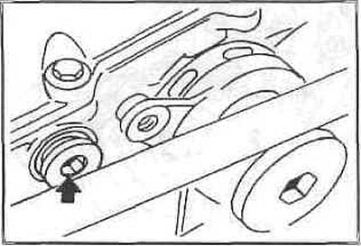
Unscrew the hydraulic V-belt tensioner and disconnect the damper.
Caution: Store the removed tensioner only in a vertical position. Otherwise, its operation may be impaired.
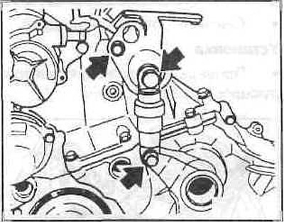
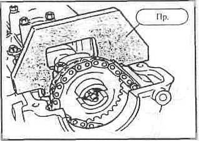
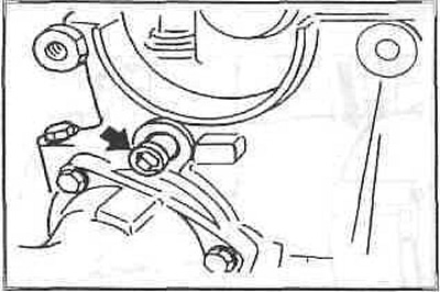
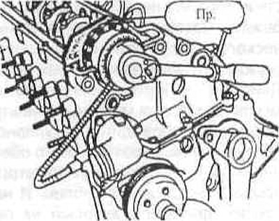
Unscrew the two bolts and remove the vacuum pump. Bolt (2) also serves to secure the chain guide.
Set the piston of the first cylinder to the top dead center position. To do this, engage fifth gear and turn the crankshaft pulley in the direction of engine rotation to a position in which the camshaft cams of the intake and exhaust valves of the first cylinder (from the drive chain side) will be facing each other. In this case, the arrows on the sprockets of both camshafts should be facing upwards.
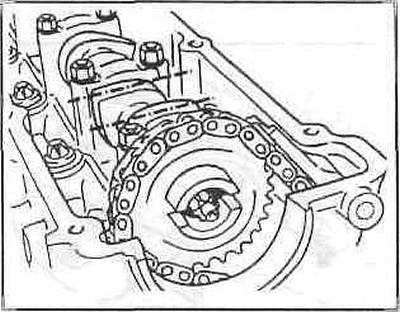
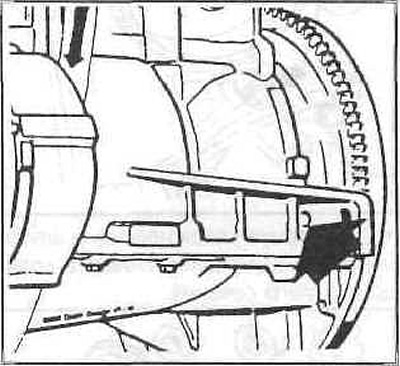
Fix the crankshaft in the top dead center position by inserting a rod through the hole in the engine block into the hole in the flywheel.
Fix the camshaft with a device. You can do without a device when unscrewing the camshaft sprocket, holding the camshaft by a 27 mm hexagon.
Insert a suitable clamping lever into the chain tensioner bar and press the tensioner down.
Unscrew the plug and fix the tensioner in a compressed state.
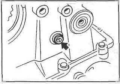
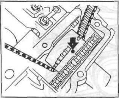
Unscrew the tension bar retaining pin from the cylinder head and remove the O-ring.
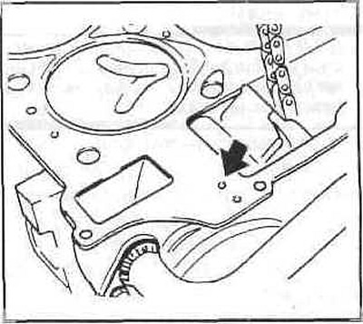
After unscrewing the chain guide retaining pin, remove the O-ring.
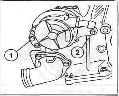
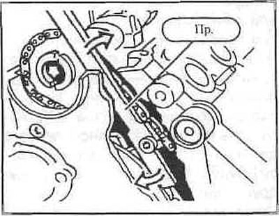
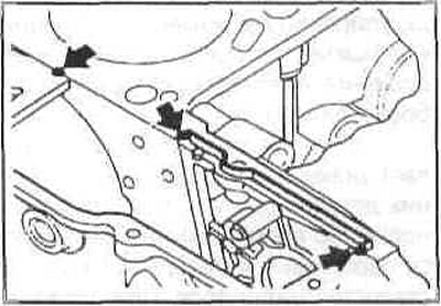
Unscrew the gearbox cover bolts. The fastening (1) is made in the form of a stud and nut.
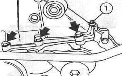
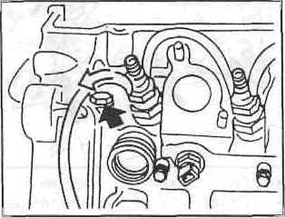
Unscrew the bolt (arrow) and also disconnect the drain hose from the nozzle.
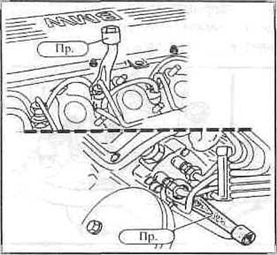
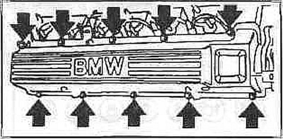
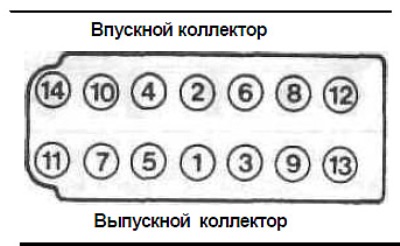
In sequence 14 to 1, first loosen the cylinder head bolts 1/2 turn, then completely loosen them.
Remove the cylinder head.
Installation
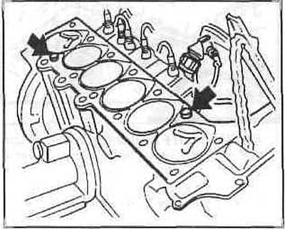
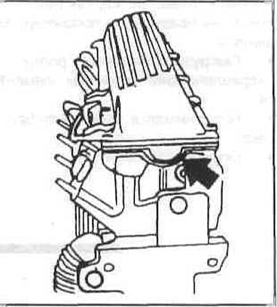
Check the position of the centering bushings (arrows).
Apply a new gasket without sealant so that it does not cover the holes. The new gasket should be the same thickness as the gasket removed.
If it is not clear which gasket to install, it is necessary to measure the piston protrusions. The gasket thickness is selected based on the maximum protrusion of one of the 6 pistons. To measure, place the dial indicator at point A and, by slightly turning the crankshaft in both directions, determine the highest position. Then repeat the measurement at point B. The average value between the measurement results at points A and B gives the "piston protrusion" value. Take these measurements on all six pistons.
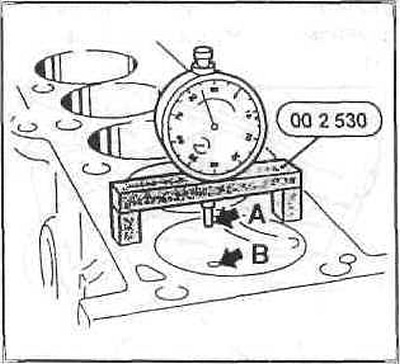
Note: However, if the piston protrusion on one or more cylinders exceeds 0.81 mm, a three-hole gasket is installed.
Install the cylinder head with the mark on the high pressure pump facing upwards.
Insert and hand tighten the cylinder head bolts, lubricated with engine oil.
The cylinder head bolts are tightened in 6 steps. At each step, tightening is performed in sequence from 1 to 14.
- Step 1: tighten with a torque wrench to 80 Nm.
- 2nd step - tighten with a wrench by 180° and then loosen the bolts.
- Step 3: tighten with a torque wrench to 50 Nm.
- Step 4: Tighten with a wrench by 90°.
- Step 5 - tighten with a wrench by 90°. After 25 minutes of engine operation (after its installation).
- Step 6: Tighten with a wrench by 90°.
Replace the sealing gasket on the high-pressure fuel pump support. Apply sealant to the joint with the gearbox cover.
Install the gearbox cover and tighten the bolts to 10 Nm.
Tighten the fasteners near the injector and also put the return fuel hose on the injector.
Screw in the two tension bar and chain guide retaining pins with new O-rings.
Screw the sprocket with the chain attached to the camshaft, do not tighten the bolt yet.
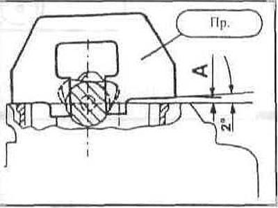
Remove the locking pin from the chain tensioner so that the chain is taut. Screw the plug into the hole in the cylinder head. To high mileage chains on the intake side of the head cylinders should be installed with a gasket (feeler gauge) of thickness A = 4.61 mm. If the template is not used, turn the camshaft approximately 2° to the left and in this position hold it by the 27mm Allen key.
In this position, tighten the camshaft sprocket two times.
- 1st step - with a torque wrench with a tightening force of 20 Nm.
- 2nd step - tighten with a hard wrench at 35°.
Insert the vacuum pump together with the O-ring, the rod should engage with the cutout in the camshaft sprocket.
Insert the shock absorber and V-belt tensioner bracket and secure.
Install the V-belt. Secure the front muffler pipe with a new gasket and new self-locking nuts to the turbocharger. Pre-coat the bolts with high-temperature paste.
Connect the wires to the glow plugs. Push the connectors until they click into place.
Insert the injection pipes. Tighten the union nuts with a special wrench to a tightening torque of 20 Nm.
Replace the intake manifold gaskets. Then install the intake manifold, tighten the bolts crosswise to 25 Nm.
Tighten the intake manifold support mounting bolts.
The diesel engine uses a wider ribbed V-belt that drives the generator, water pump and power steering pump.
This article is available at russian, bulgarian, belarusian, ukrainian, serbian, croatian, romanian, polish, slovak, hungarian
Article verified: Sevastyanov Nikolay
Share information:
Previous articles
БМВ E32: Minor engine repair
Next articles
Cylinder head of the M70 series gasoline engine — removal and…
Valve clearances of gasoline engines of the M52 series
Cylinder head of gasoline engines of the M52 series — removal and…
Cylinder head cover for M52 series petrol engines — removal and…
Minor repairs of M52 series petrol engines. General description
Valve clearances of gasoline engines of the M52 series
Cylinder head of gasoline engines of the M52 series — removal and…
Cylinder head cover for M52 series petrol engines — removal and…
Minor repairs of M52 series petrol engines. General description
Similar articles on other types of BMW cars:
Removal and installation the cylinder head. Models 318tds/325td… BMW 3 Series E36 (1990-2000)
Removal and installation the cylinder head BMW 3 Series E30 (1982-1994)
Removal and installation the cylinder head — M50 engine (models 520i,… BMW 5 Series E34 (1988-1996)
Removal and installation the cylinder head (only M52TU engine… BMW 5 Series E39 (1995-2003)
Removal and installation the cylinder head BMW X3 E83 (2003-2010)
Removal and installation the engine BMW X5 E53 (1999-2006)
Link in different formats to this page
Visitor comments
No comments yet
- General information
- Introduction to guide
- Manual
- Maintenance
- Power unit
- Engine M60/1, M60/2 (petrol)
- M62 engine (petrol)
- M57 engine (diesel)
- M67 engine (diesel)
- Cooling system
- Fuel system (petrol)
- Fuel system (diesel)
- Exhaust system
- Ignition and control systems
- Charge and launch systems
- Transmission
- Clutch
- Mechanical gearbox
- Automatic gearbox
- Cardan and drive shafts
- Chassis
- Brake system
- Front suspension
- Rear suspension
- Steering
- Body
- Exterior
- Interior
- Electrical equipment
- Equipment and devices
- Lighting
- Heating and air conditioning
- Electrical circuits
- General information
- Care and maintenance
- Power unit
- Minor engine repair
- Engine overhaul
- Lubrication system
- Cooling system
- Ignition system
- Supply system
- Injection system (petrol)
- Injection system (diesel)
- Exhaust system
- Transmission
- Clutch
- Manual gearbox
- Automatic gearbox
- Cardan gear
- Rear axle and shafts
- Chassis
- Front suspension
- Rear suspension
- Steering
- Wheels and tires
- Brake system
- Body
- Body elements
- Electrical equipment
- Equipment and devices
- Electrical circuits