
- Home
- BMW 3 Series
- E30
- Power unit
- Supply system
- Removal and installation the air filter
Removal and installation the air filter (BMW 3 Series E30)
Removal
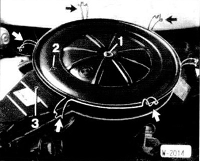
Unscrew bolt "1".
Open the quick release latches (arrows) and remove the air filter cover.
Remove the filter element.
Loosen the nuts (arrows) securing the air filter housing.
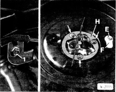
Remove the fastening -H.
Unscrew nut "1" of the intake system support.
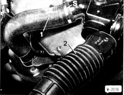
Disconnect the outside air hose "2" and the warm air hose "1", having first completely loosened the clamps "S".
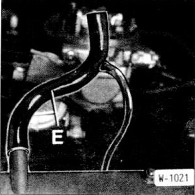
Disconnect the engine crankcase ventilation hose "E", the hose of the valve metering additional air in the forced idle mode, and also the vacuum hose at the bottom of the air filter housing.
Remove the air filter housing.
Installation
Connect the engine crankcase ventilation hose, the hose of the valve metering additional air in the forced idle mode, and the vacuum hose at the bottom of the air filter housing.
Place the air filter housing, apply the mounting ring and screw it on.
Secure the intake system support to the bracket.
Connect the outside air hose and the warm air hose, securing them with clamps.
Insert the filter element.
Place the cover so that arrows "2" and "3" in Figure W-2014 point towards each other.
Screw on the air filter cover and secure with quick-release fasteners.
Checking the intake air heating
Heating of the intake air depends on the temperature and is regulated by the air damper in the air intake. If there is a defect in the heating system, the following malfunctions may occur:
- Violations of the idle mode during the warm-up phase.
- Transient disturbances.
- Insufficient power, maximum speed is not reached.
- High fuel consumption.
Checking the position of the air damper
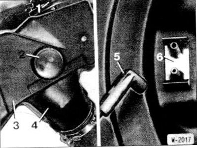
The position of the air damper is controlled through the inspection window "2" in the air intake "3".
When the engine is running cold, the damper should open the warm air channel "4" so that warm air flows from the exhaust manifold to the air filter.
As the engine warms up, the air damper gradually closes the warm air channel and simultaneously opens the outside air channel.
When the engine reaches operating temperature, the warm air channel is completely blocked. Only outside air enters the engine. Otherwise, check the membrane box.
Checking the membrane box
Check the reliability of the fastening of the vacuum hoses between the membrane box and the temperature regulator and between the temperature regulator and the intake manifold.
When bending the hoses, check for cracks and damage; if necessary, replace damaged hoses.
Disconnect the hose "5" from the temperature regulator "6" at the bottom of the air filter housing and check the operation of the air damper by sucking it in with your mouth. If the damper opens, clean the holes "E" and "F" of the temperature regulator (drawing W-2015). If necessary, replace the temperature controller.
If the air damper remains closed, replace the diaphragm box.
At the service station, a vacuum pump with a connected pressure gauge is used to check the membrane box. The pump is connected to the hose "5" and thus creates a vacuum at the membrane box. Up to a vacuum of 70±10 mbar, the warm air channel must remain closed, starting from a value of 140±10 mbar, it must be open. In the removed position, the adjustment lever of the membrane box at a vacuum of about 300 mbar must be completely recessed and the vacuum must not decrease.
(The original material is located on the website «BMWman»)
This article is available at russian, bulgarian, belarusian, ukrainian, serbian, croatian, romanian, polish, slovak, hungarian
Article verified: Polikarpov Saveliy
Share information:
Previous articles
БМВ E30: Supply system
Next articles
Similar articles on other types of BMW cars:
Removal and installation the air filter housing / air flow meter BMW 5 Series E34 (1988-1996)
Removal and installation the air filter housing / mass air flow meter BMW 5 Series E39 (1995-2003)
Air Filter Housing/Air Flow Meter — Removal and Installation BMW 7 Series E32 (1986-1994)
Removal and installation the ATF filter and hydraulic unit BMW 7 Series E38 (1994-2001)
Pistons — removal and installation BMW X3 E83 (2003-2010)
Removal and installation the engine BMW X5 E53 (1999-2006)
Link in different formats to this page
Visitor comments
No comments yet
- General information
- Manual
- Maintenance
- Power unit
- Engine repair
- Cooling system
- Power system (gasoline)
- Injection system (gasoline)
- Fuel system (diesel)
- Exhaust system
- Ignition system
- Charge and launch systems
- Transmission
- Car gearbox
- Clutch and drive shafts
- Chassis
- Brake system
- Suspension front and rear
- Steering
- Body
- Body care and repair
- Exterior
- Interior
- Electrical equipment
- Troubleshooting
- Lighting and signaling
- Equipment and devices
- Heater and air conditioner
- Electrical circuits
- General information
- Manual
- Repair on the road
- Weekly checks
- Maintenance
- Troubleshooting
- Power unit
- 4 cylinder engines
- 6 cylinder engines
- Engine overhaul
- Cooling and heating
- Fuel and exhaust system
- Starting and charging system
- Ignition system
- Transmission
- Clutch
- Mechanical gearbox
- Automatic gearbox
- Cardan and drive shafts
- Chassis
- Brake system
- Wheel suspension
- Steering
- Body
- Exterior
- Interior
- Electrical equipment
- Equipment and devices
- Electrical circuits
- General information
- Maintenance
- Power unit
- Engine repair
- Cooling system
- Ignition system
- Supply system
- Fuel injection system
- Exhaust system
- Transmission
- Clutch
- Car gearbox
- Front and rear axle
- Chassis
- Steering
- Brake system
- Body
- Exterior
- Interior
- Electrical equipment
- Heating system
- Equipment and devices
- Power devices
- Electrical circuits
- Power unit
- M10/M20 engine
- M40 engine
- Ignition system
- Lubrication system
- Cooling system
- Supply system
- Fuel injection
- Exhaust system
- Transmission
- Clutch
- Manual gearbox
- Front axle
- Rear axle
- Chassis
- Steering
- Brake system
- Body
- Exterior
- Interior
- Electrical equipment
- Heating system
- Equipment and devices
- Electrical circuits
- General information
- Specifications
- Operation and maintenance
- 4-cylinder engine
- Engine repair
- Cooling and lubrication system
- Supply system
- Ignition system
- 6-cylinder engine
- Engine repair
- Cooling and lubrication system
- Supply system
- Fuel injection system
- Ignition system
- Transmission
- Clutch
- 4-speed manual gearbox
- 5-speed manual gearbox
- Automatic gearbox
- Cardan and rear axle
- Chassis
- Steering
- Front suspension
- Rear suspension
- Brake system
- Electrical equipment
- Equipment and devices
- Electrical circuits