
- Home
- BMW 3 Series
- E30
- Power unit
- Supply system
- Removal and installation, checking of the throttle valve regulator
Removal and installation, checking of the throttle valve regulator (BMW 3 Series E30)
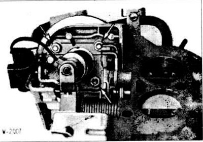
The throttle valve regulator is required for automatic control of engine starting, warming up, operation at maximum speed, idle speed, shutdown in forced running mode and when turning off the engine.
The throttle valve regulator is an electropneumatic regulator controlled by the carburetor control unit and accordingly regulating the position of the throttle valve in a certain range. The regulation range extends from increased idle speed to complete closure of the throttle valve, i.e. to shutdown in the forced idle mode and to engine shutdown. The regulator pusher is adjacent to the throttle valve lever and can move under the action of the vacuum membrane, overcoming the resistance of the return spring of the regulator. The required working pressure is regulated by 2 electromagnetic valves, whereby one valve supplies the vacuum of the intake pipe, and the second valve - atmospheric pressure. Depending on the state of the valves, determined by the control unit, the pressure applied to the membrane and, consequently, the position of the pusher continuously change.
As soon as the driver gives the gas, the idle switch in the front part of the pushrod closes and thus sends information to the control unit about the throttle lever moving away from the pushrod.
Remove the air filter (see section "Removal and installation the air filter").
Disconnect the vacuum hose and vent tube from the throttle control valve.
Disconnect the connector, first opening the retaining clip.
Disconnect the idle speed switch connector.
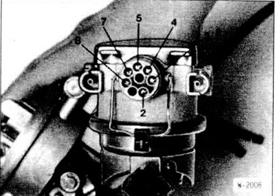
Unscrew 3 nuts (arrows) and remove the throttle valve regulator.
Screw in the throttle valve regulator, lightly tightening the screws to a torque of 3 Nm. and perform a basic adjustment.
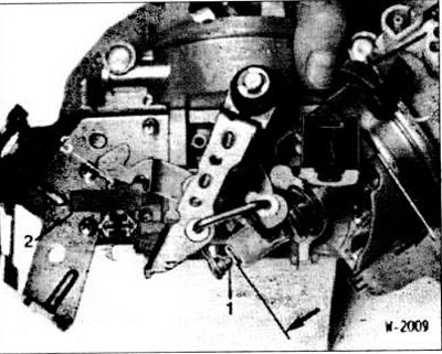
Remove the stop screw "1" of the pushrod from the throttle lever and replace it with a new screw.
Disconnect the temperature sensor connector and short-circuit the connector contacts with a piece of wire.
Apply a vacuum of approximately 250 mbar through the "U" connection of the throttle valve regulator. The vacuum must be maintained constant.
Turn on the ignition.
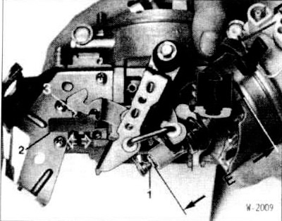
Screw in the stop screw "1" of the tappet so that the BMW 131110 tool can be moved between the over-idle stop and the over-idle stop screw with tension. The throttle valve regulator must not function in this case. Finally, separate the screw head from the stop screw of the tappet "1".
Connect the idle switch and throttle control connector and secure them with the retaining clips.
Connect the vacuum hose and vent tube to the throttle control valve.
Install the air filter (see section "Removal and installation the air filter").
Check the idle speed and CO content. For the specified value, see the table in the "Ignition system" section.
The test is carried out in the removed state.
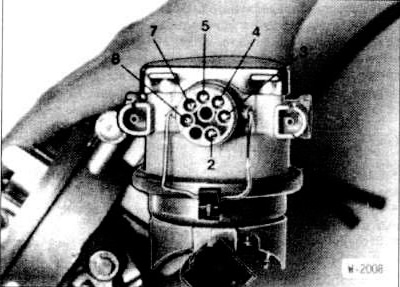
Apply battery voltage to terminals 2(+) and 3(-) via auxiliary wires: this opens the electromagnetic valve.
Connect an ohmmeter to terminals 4 and 7.
Apply vacuum to the "U" fitting of the throttle valve regulator; in this case, the membrane pulls in the pusher, overcoming the force of the spring. Increase the vacuum with a vacuum pump until the ohmmeter reading increases from 500 to 700 Ohms.
After this, remove the wire from contact 3. This will close the valve.
Disconnect the vacuum hose from the "U" fitting.
The ohmmeter readings should not change by more than 200 0 m within 1 minute, otherwise replace the throttle valve regulator.
Apply a vacuum of approximately 250 mbar through the "U" connection of the throttle valve regulator. The vacuum must be maintained constant.
Apply battery voltage to terminals 2(+) and 3(-). The plunger should quickly retract within a maximum of 1 second.
Remove the wire from terminal 3 and turn off the vacuum pump.
Measure the distance "E" (drawing W-2009). Do not use the idle switch.
Apply ground to terminal 8. This will allow air to enter the throttle valve regulator and the pusher should pop out in a maximum of 1 second.
Measure the distance to the throttle body.
If the response time or stroke differs from the values specified in the carburetor main technical data table, replace the throttle valve adjuster.
Connect an ohmmeter to the idle switch connector contacts. When pressing the switch, the resistance should be 0, in the opposite state - infinity.

Check the resistance of the vacuum valve by connecting an ohmmeter to terminals 2 and 3.
Check the air valve resistance by connecting an ohmmeter to terminals 2 and 8.
Check the total resistance of the potentiometer by connecting an ohmmeter to terminals 4 and 5.
Check the engine resistance by connecting an ohmmeter to terminals 4 and 7. Then slowly push the pusher in; the resistance should decrease. Measure the resistance with the plunger fully recessed.
If the resistance values deviate from the specified values, replace the throttle valve controller. For the specified values, see the table of main carburetor technical data.
[The original article is posted on the resource: BMWMan.ru]
The throttle valve regulator is an electropneumatic regulator controlled by the carburetor control unit and accordingly regulating the position of the throttle valve in a certain range. The regulation range extends from increased idle speed to complete closure of the throttle valve, i.e. to shutdown in the forced idle mode and to engine shutdown. The regulator pusher is adjacent to the throttle valve lever and can move under the action of the vacuum membrane, overcoming the resistance of the return spring of the regulator. The required working pressure is regulated by 2 electromagnetic valves, whereby one valve supplies the vacuum of the intake pipe, and the second valve - atmospheric pressure. Depending on the state of the valves, determined by the control unit, the pressure applied to the membrane and, consequently, the position of the pusher continuously change.
As soon as the driver gives the gas, the idle switch in the front part of the pushrod closes and thus sends information to the control unit about the throttle lever moving away from the pushrod.
Removal
Remove the air filter (see section "Removal and installation the air filter").
Disconnect the vacuum hose and vent tube from the throttle control valve.
Disconnect the connector, first opening the retaining clip.
Disconnect the idle speed switch connector.
Unscrew 3 nuts (arrows) and remove the throttle valve regulator.
Installation
Screw in the throttle valve regulator, lightly tightening the screws to a torque of 3 Nm. and perform a basic adjustment.
Basic adjustment
Remove the stop screw "1" of the pushrod from the throttle lever and replace it with a new screw.
Disconnect the temperature sensor connector and short-circuit the connector contacts with a piece of wire.
Apply a vacuum of approximately 250 mbar through the "U" connection of the throttle valve regulator. The vacuum must be maintained constant.
Turn on the ignition.
Screw in the stop screw "1" of the tappet so that the BMW 131110 tool can be moved between the over-idle stop and the over-idle stop screw with tension. The throttle valve regulator must not function in this case. Finally, separate the screw head from the stop screw of the tappet "1".
Connect the idle switch and throttle control connector and secure them with the retaining clips.
Connect the vacuum hose and vent tube to the throttle control valve.
Install the air filter (see section "Removal and installation the air filter").
Check the idle speed and CO content. For the specified value, see the table in the "Ignition system" section.
Examination
The test is carried out in the removed state.
Checking for leaks
Apply battery voltage to terminals 2(+) and 3(-) via auxiliary wires: this opens the electromagnetic valve.
Connect an ohmmeter to terminals 4 and 7.
Apply vacuum to the "U" fitting of the throttle valve regulator; in this case, the membrane pulls in the pusher, overcoming the force of the spring. Increase the vacuum with a vacuum pump until the ohmmeter reading increases from 500 to 700 Ohms.
After this, remove the wire from contact 3. This will close the valve.
Disconnect the vacuum hose from the "U" fitting.
The ohmmeter readings should not change by more than 200 0 m within 1 minute, otherwise replace the throttle valve regulator.
Checking the working stroke and response time
Apply a vacuum of approximately 250 mbar through the "U" connection of the throttle valve regulator. The vacuum must be maintained constant.
Apply battery voltage to terminals 2(+) and 3(-). The plunger should quickly retract within a maximum of 1 second.
Note: There is a check valve located behind the "U" fitting, which prevents fuel vapors from entering the electric valve.
Remove the wire from terminal 3 and turn off the vacuum pump.
Measure the distance "E" (drawing W-2009). Do not use the idle switch.
Apply ground to terminal 8. This will allow air to enter the throttle valve regulator and the pusher should pop out in a maximum of 1 second.
Measure the distance to the throttle body.
If the response time or stroke differs from the values specified in the carburetor main technical data table, replace the throttle valve adjuster.
Checking the idle switch
Connect an ohmmeter to the idle switch connector contacts. When pressing the switch, the resistance should be 0, in the opposite state - infinity.
Checking the throttle control resistance
Check the resistance of the vacuum valve by connecting an ohmmeter to terminals 2 and 3.
Check the air valve resistance by connecting an ohmmeter to terminals 2 and 8.
Check the total resistance of the potentiometer by connecting an ohmmeter to terminals 4 and 5.
Check the engine resistance by connecting an ohmmeter to terminals 4 and 7. Then slowly push the pusher in; the resistance should decrease. Measure the resistance with the plunger fully recessed.
If the resistance values deviate from the specified values, replace the throttle valve controller. For the specified values, see the table of main carburetor technical data.
[The original article is posted on the resource: BMWMan.ru]
This article is available at russian, bulgarian, belarusian, ukrainian, serbian, croatian, romanian, polish, slovak, hungarian
Article verified: Polikarpov Saveliy
Share information:
Previous articles
БМВ E30: Supply system
Next articles
Similar articles on other types of BMW cars:
Removal and installation, checking of the idle speed control valve BMW 5 Series E34 (1988-1996)
Removal and installation the throttle valve pipe BMW 5 Series E39 (1995-2003)
Removal and installation the preheating valve BMW 7 Series E38 (1994-2001)
Thermostat — Removal, Installation and Checking BMW 7 Series E32 (1986-1994)
Pistons — removal and installation BMW X3 E83 (2003-2010)
Removal and installation the engine BMW X5 E53 (1999-2006)
Link in different formats to this page
Visitor comments
No comments yet
- General information
- Manual
- Maintenance
- Power unit
- Engine repair
- Cooling system
- Power system (gasoline)
- Injection system (gasoline)
- Fuel system (diesel)
- Exhaust system
- Ignition system
- Charge and launch systems
- Transmission
- Car gearbox
- Clutch and drive shafts
- Chassis
- Brake system
- Suspension front and rear
- Steering
- Body
- Body care and repair
- Exterior
- Interior
- Electrical equipment
- Troubleshooting
- Lighting and signaling
- Equipment and devices
- Heater and air conditioner
- Electrical circuits
- General information
- Manual
- Repair on the road
- Weekly checks
- Maintenance
- Troubleshooting
- Power unit
- 4 cylinder engines
- 6 cylinder engines
- Engine overhaul
- Cooling and heating
- Fuel and exhaust system
- Starting and charging system
- Ignition system
- Transmission
- Clutch
- Mechanical gearbox
- Automatic gearbox
- Cardan and drive shafts
- Chassis
- Brake system
- Wheel suspension
- Steering
- Body
- Exterior
- Interior
- Electrical equipment
- Equipment and devices
- Electrical circuits
- General information
- Maintenance
- Power unit
- Engine repair
- Cooling system
- Ignition system
- Supply system
- Fuel injection system
- Exhaust system
- Transmission
- Clutch
- Car gearbox
- Front and rear axle
- Chassis
- Steering
- Brake system
- Body
- Exterior
- Interior
- Electrical equipment
- Heating system
- Equipment and devices
- Power devices
- Electrical circuits
- Power unit
- M10/M20 engine
- M40 engine
- Ignition system
- Lubrication system
- Cooling system
- Supply system
- Fuel injection
- Exhaust system
- Transmission
- Clutch
- Manual gearbox
- Front axle
- Rear axle
- Chassis
- Steering
- Brake system
- Body
- Exterior
- Interior
- Electrical equipment
- Heating system
- Equipment and devices
- Electrical circuits
- General information
- Specifications
- Operation and maintenance
- 4-cylinder engine
- Engine repair
- Cooling and lubrication system
- Supply system
- Ignition system
- 6-cylinder engine
- Engine repair
- Cooling and lubrication system
- Supply system
- Fuel injection system
- Ignition system
- Transmission
- Clutch
- 4-speed manual gearbox
- 5-speed manual gearbox
- Automatic gearbox
- Cardan and rear axle
- Chassis
- Steering
- Front suspension
- Rear suspension
- Brake system
- Electrical equipment
- Equipment and devices
- Electrical circuits