
- Home
- BMW 3 Series
- E30
- Power unit
- M40 engine
- Checking/adjusting valve clearances
Checking/adjusting valve clearances (BMW 3 Series E30)
To compensate for thermal expansion in the valve drive, a certain valve clearance must be provided.
If the clearance is too small, the valve timing changes, compression deteriorates, engine power decreases, and the engine runs unevenly. In extreme cases, the valves may become deformed or the valve seats may burn out.
With increased clearances, strong mechanical knocks occur, the valve timing changes, due to a decrease in valve opening time and thus a deterioration in cylinder filling, engine power decreases, and the engine runs unevenly.
Adjusting valve clearances is only successful when there is adequate valve sealing, there is no unacceptable play in the valve guides and the ends of the valve stems are not broken.
The four-cylinder engines of the 318i and 318is models produced since September 1987, and the 316i models produced since September 1988, have hydraulic valve clearance compensators. Valve clearance adjustment work is not performed on them.
Checking and adjusting valve clearances is performed as part of maintenance every 20,000 km.
Checking and adjusting valve clearances can be done on both a cold and a warm engine.
Remove the air filter (see section "Removing and installing the air filter").
Remove the cylinder head cover (see section "Removing and installing the cylinder head cover").
Put the gearbox in neutral (tighten the handbrake).
Turn the engine with a 27/30 mm wrench on the central bolt of the crankshaft pulley in the direction of engine rotation. This also turns the camshaft.
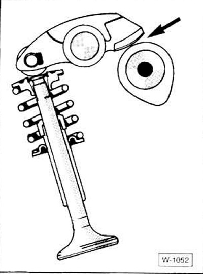
Align the camshaft so that the cam lobe is on the opposite side from the rocker arm of the valve being tested; in this case, the cam forming circle is adjacent to the rocker arm.
It is advisable to start checking with the valves of the 1st cylinder, located in the front part of the engine, setting this cylinder to the top dead center position. After this, the engine is turned further (on a four-cylinder engine by half a turn) and the valves of the next cylinder are checked, in accordance with the firing sequence. The firing sequence on a four-cylinder engine is: 1-3-4-2; on a six-cylinder engine: 1-5-3-6-2-4.
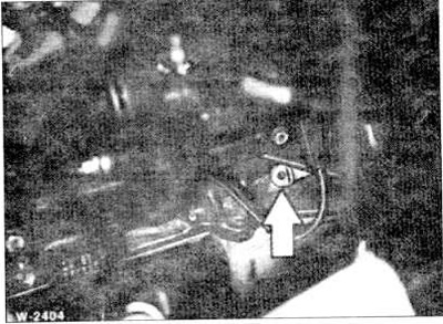
Another option for adjusting valve clearances: engage 4th gear, release the handbrake. Move the car a little until the cam moves away from one of the valves. The cam is set at an angle downwards. In this case, the cam does not press on the rocker arm (see picture). In this position, measure the valve clearance and adjust it if necessary.
Mark the rocker arm with a marker.
Move the car a little further until another cam moves away from the rocker arm. In this case, the sequence of adjusting the valve clearances is irrelevant. The rocker arms are marked so as not to check the valve clearance again by mistake.
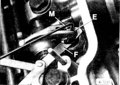
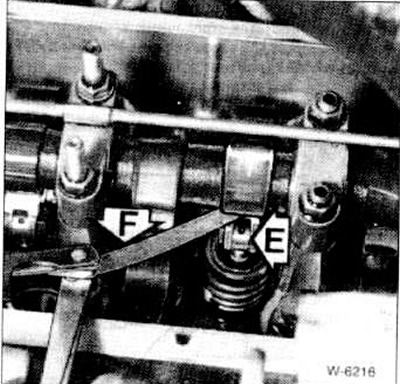
Petrol engines: measure the valve clearance with feeler gauge "F" inserted between eccentric "E" and the end of the valve stem.
Diesel engines models 324d, 324td: measure the valve clearance with feeler gauge "F" between the cam and the rocker arm.
The valve clearance is adjusted correctly if the feeler gauge fits tightly.
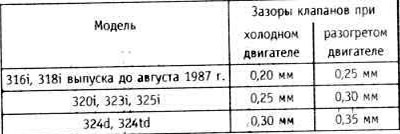
For testing, take a probe with a size exceeding the specified one (see table) by 0.05 mm. Ohm should not enter between the valve and the rocker arm. If it does, reduce the valve clearance. Note: The specified clearance values for the intake and exhaust valves are the same.
"Cold" is an engine with a coolant temperature below 35°C. When adjusting valve clearances on a "warmed up" engine, the coolant temperature should be about 80°C. A sign of a "warmed up" engine is a warm lower radiator water hose. The thermostat just opens the large coolant circulation circuit.
If the valve clearance differs from the specified value, insert the BMW 113070 rod into the eccentric hole, loosen the "M" nut and turn the eccentric with the rod until the specified valve clearance is reached. If the BMW tool is not available, a thin screwdriver of the appropriate diameter can be used.
Tighten the lock nut to a torque of approximately 10 Nm (estimated value), while holding the eccentric.
Check the valve clearance again and crank the engine further.
Check or adjust the clearances of the remaining valves in the same way.
Install the cylinder head cover (see section "Removing and installing the cylinder head cover")
Install the air filter, see (section "Removing and installing the air filter").
To check, you need a dial indicator with a corresponding adapter for screwing into the pump.
Disconnect the ground wire from the battery.
Raise the front of the car.
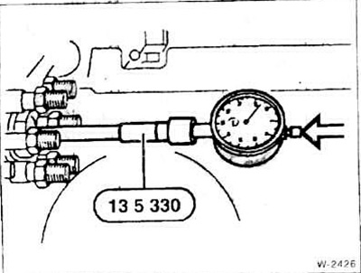
Unscrew the middle plug on the high-pressure fuel pump. Screw in the adapter instead of the plug (BMW 135330) and the arrow indicator and press it slightly.
Turn the crankshaft clockwise towards the top dead center of the 1st cylinder until the indicator arrow shows the minimum value for some time. The crankshaft should turn 60-90° before the top dead center. The piston of the 1st cylinder is in the top dead center position when both its cams of the 1st cylinder on the toothed belt side are facing up. To check, unscrew the oil filler cap and observe the camshaft.
To turn the engine, engage 5th gear, release the handbrake and move the car, or tighten the handbrake and turn the crankshaft pulley with the wrench head on the central bolt.
Set the dial indicator scale to "O".
Remove the plug from the engine block.
Turn the crankshaft until the support rod BMW 112300) can enter the flywheel hole (top dead center position).
The reading of the dial gauge should be 1.05±0.02 mm. Otherwise, adjust the high-pressure fuel pump. On the 324d model produced before November 1988 (without DDE), the specified value is 0.74+0.02 mm.
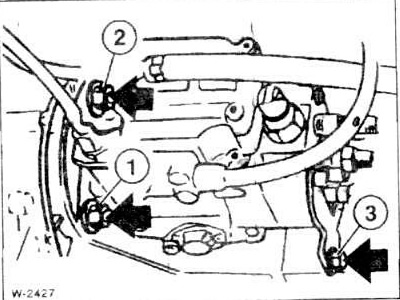
Loosen the fastening of the 2 rear bolts "3" without unscrewing them (the second bolt "3" is not visible in the figure).
Loosen nuts "1" and "2".
Turn the high pressure fuel pump until the specified value is reached on the dial gauge scale.
Tighten nuts and bolts in sequence 1–3 to a torque of 25 Nm.
Check the adjustment again by removing the rod and first turning the crankshaft back 90°.
Remove the dial indicator.
Tighten the central plug with a new gasket using a tightening torque of 15 Nm.
After the test drive, check the tightness of the central plug and, if necessary, tighten it to a maximum tightening torque of 20 Nm.
If the clearance is too small, the valve timing changes, compression deteriorates, engine power decreases, and the engine runs unevenly. In extreme cases, the valves may become deformed or the valve seats may burn out.
With increased clearances, strong mechanical knocks occur, the valve timing changes, due to a decrease in valve opening time and thus a deterioration in cylinder filling, engine power decreases, and the engine runs unevenly.
Adjusting valve clearances is only successful when there is adequate valve sealing, there is no unacceptable play in the valve guides and the ends of the valve stems are not broken.
The four-cylinder engines of the 318i and 318is models produced since September 1987, and the 316i models produced since September 1988, have hydraulic valve clearance compensators. Valve clearance adjustment work is not performed on them.
Checking and adjusting valve clearances is performed as part of maintenance every 20,000 km.
Checking and adjusting valve clearances can be done on both a cold and a warm engine.
Examination
Remove the air filter (see section "Removing and installing the air filter").
Remove the cylinder head cover (see section "Removing and installing the cylinder head cover").
Put the gearbox in neutral (tighten the handbrake).
Turn the engine with a 27/30 mm wrench on the central bolt of the crankshaft pulley in the direction of engine rotation. This also turns the camshaft.
Align the camshaft so that the cam lobe is on the opposite side from the rocker arm of the valve being tested; in this case, the cam forming circle is adjacent to the rocker arm.
It is advisable to start checking with the valves of the 1st cylinder, located in the front part of the engine, setting this cylinder to the top dead center position. After this, the engine is turned further (on a four-cylinder engine by half a turn) and the valves of the next cylinder are checked, in accordance with the firing sequence. The firing sequence on a four-cylinder engine is: 1-3-4-2; on a six-cylinder engine: 1-5-3-6-2-4.
Another option for adjusting valve clearances: engage 4th gear, release the handbrake. Move the car a little until the cam moves away from one of the valves. The cam is set at an angle downwards. In this case, the cam does not press on the rocker arm (see picture). In this position, measure the valve clearance and adjust it if necessary.
Mark the rocker arm with a marker.
Move the car a little further until another cam moves away from the rocker arm. In this case, the sequence of adjusting the valve clearances is irrelevant. The rocker arms are marked so as not to check the valve clearance again by mistake.
Petrol engines: measure the valve clearance with feeler gauge "F" inserted between eccentric "E" and the end of the valve stem.
Diesel engines models 324d, 324td: measure the valve clearance with feeler gauge "F" between the cam and the rocker arm.
The valve clearance is adjusted correctly if the feeler gauge fits tightly.
For testing, take a probe with a size exceeding the specified one (see table) by 0.05 mm. Ohm should not enter between the valve and the rocker arm. If it does, reduce the valve clearance. Note: The specified clearance values for the intake and exhaust valves are the same.
"Cold" is an engine with a coolant temperature below 35°C. When adjusting valve clearances on a "warmed up" engine, the coolant temperature should be about 80°C. A sign of a "warmed up" engine is a warm lower radiator water hose. The thermostat just opens the large coolant circulation circuit.
Adjustment
If the valve clearance differs from the specified value, insert the BMW 113070 rod into the eccentric hole, loosen the "M" nut and turn the eccentric with the rod until the specified valve clearance is reached. If the BMW tool is not available, a thin screwdriver of the appropriate diameter can be used.
Tighten the lock nut to a torque of approximately 10 Nm (estimated value), while holding the eccentric.
Check the valve clearance again and crank the engine further.
Check or adjust the clearances of the remaining valves in the same way.
Install the cylinder head cover (see section "Removing and installing the cylinder head cover")
Install the air filter, see (section "Removing and installing the air filter").
Adjusting the start moment of the high pressure fuel pump on a diesel engine
To check, you need a dial indicator with a corresponding adapter for screwing into the pump.
Disconnect the ground wire from the battery.
Raise the front of the car.
Unscrew the middle plug on the high-pressure fuel pump. Screw in the adapter instead of the plug (BMW 135330) and the arrow indicator and press it slightly.
Turn the crankshaft clockwise towards the top dead center of the 1st cylinder until the indicator arrow shows the minimum value for some time. The crankshaft should turn 60-90° before the top dead center. The piston of the 1st cylinder is in the top dead center position when both its cams of the 1st cylinder on the toothed belt side are facing up. To check, unscrew the oil filler cap and observe the camshaft.
To turn the engine, engage 5th gear, release the handbrake and move the car, or tighten the handbrake and turn the crankshaft pulley with the wrench head on the central bolt.
Set the dial indicator scale to "O".
Remove the plug from the engine block.
Turn the crankshaft until the support rod BMW 112300) can enter the flywheel hole (top dead center position).
Caution: Do not turn the crankshaft against the direction of engine rotation. This will cause distortion of measurements.
The reading of the dial gauge should be 1.05±0.02 mm. Otherwise, adjust the high-pressure fuel pump. On the 324d model produced before November 1988 (without DDE), the specified value is 0.74+0.02 mm.
Loosen the fastening of the 2 rear bolts "3" without unscrewing them (the second bolt "3" is not visible in the figure).
Loosen nuts "1" and "2".
Caution: Do not loosen the nuts too much to avoid changing the timing belt tension.
Turn the high pressure fuel pump until the specified value is reached on the dial gauge scale.
Tighten nuts and bolts in sequence 1–3 to a torque of 25 Nm.
Check the adjustment again by removing the rod and first turning the crankshaft back 90°.
Remove the dial indicator.
Tighten the central plug with a new gasket using a tightening torque of 15 Nm.
Caution: Remove the support rod from the engine flywheel. Install the plug.
After the test drive, check the tightness of the central plug and, if necessary, tighten it to a maximum tightening torque of 20 Nm.
This article is available at russian, bulgarian, belarusian, ukrainian, serbian, croatian, romanian, polish, slovak, hungarian
Article verified: Polikarpov Saveliy
Share information:
Previous articles
БМВ E30: M40 engine
Next articles
Similar articles on other types of BMW cars:
Checking/adjusting valve clearances BMW 5 Series E34 (1988-1996)
Checking and adjusting valve clearances BMW 5 Series E28 (1981-1988)
Valve clearances BMW 7 Series E32 (1986-1994)
Checking the condition of the windshield wipers and adjusting the… BMW 7 Series E38 (1994-2001)
Adjusting the valve timing BMW X3 E83 (2003-2010)
Checking and adjusting valve timing BMW X5 E53 (1999-2006)
Link in different formats to this page
Visitor comments
No comments yet
- General information
- Manual
- Maintenance
- Power unit
- Engine repair
- Cooling system
- Power system (gasoline)
- Injection system (gasoline)
- Fuel system (diesel)
- Exhaust system
- Ignition system
- Charge and launch systems
- Transmission
- Car gearbox
- Clutch and drive shafts
- Chassis
- Brake system
- Suspension front and rear
- Steering
- Body
- Body care and repair
- Exterior
- Interior
- Electrical equipment
- Troubleshooting
- Lighting and signaling
- Equipment and devices
- Heater and air conditioner
- Electrical circuits
- General information
- Manual
- Repair on the road
- Weekly checks
- Maintenance
- Troubleshooting
- Power unit
- 4 cylinder engines
- 6 cylinder engines
- Engine overhaul
- Cooling and heating
- Fuel and exhaust system
- Starting and charging system
- Ignition system
- Transmission
- Clutch
- Mechanical gearbox
- Automatic gearbox
- Cardan and drive shafts
- Chassis
- Brake system
- Wheel suspension
- Steering
- Body
- Exterior
- Interior
- Electrical equipment
- Equipment and devices
- Electrical circuits
- General information
- Maintenance
- Power unit
- Engine repair
- Cooling system
- Ignition system
- Supply system
- Fuel injection system
- Exhaust system
- Transmission
- Clutch
- Car gearbox
- Front and rear axle
- Chassis
- Steering
- Brake system
- Body
- Exterior
- Interior
- Electrical equipment
- Heating system
- Equipment and devices
- Power devices
- Electrical circuits
- Power unit
- M10/M20 engine
- M40 engine
- Ignition system
- Lubrication system
- Cooling system
- Supply system
- Fuel injection
- Exhaust system
- Transmission
- Clutch
- Manual gearbox
- Front axle
- Rear axle
- Chassis
- Steering
- Brake system
- Body
- Exterior
- Interior
- Electrical equipment
- Heating system
- Equipment and devices
- Electrical circuits
- General information
- Specifications
- Operation and maintenance
- 4-cylinder engine
- Engine repair
- Cooling and lubrication system
- Supply system
- Ignition system
- 6-cylinder engine
- Engine repair
- Cooling and lubrication system
- Supply system
- Fuel injection system
- Ignition system
- Transmission
- Clutch
- 4-speed manual gearbox
- 5-speed manual gearbox
- Automatic gearbox
- Cardan and rear axle
- Chassis
- Steering
- Front suspension
- Rear suspension
- Brake system
- Electrical equipment
- Equipment and devices
- Electrical circuits