
External inspection of oil leaks
In case of engine oil flooding and with increased oil consumption, determine the places of its leakage. To do this, check the engine in the following places:
- Open the filler cap and check the gasket for cracks or damage.
- Crankcase ventilation: ventilation hoses from the crankcase to the camshaft housing and from the camshaft housing to the air manifold housing.
- Cylinder head cover gasket.
- Cylinder head gasket.
- Place of connection of a flange of the distributor of ignition.
- Oil filter gasket: between oil filter and flange.
- Oil drain plug (pad).
- Oil pan gasket.
- Connecting the engine to the gearbox (gasket on flywheel or gearbox shaft).
Since the leaking oil spreads over a large area of the engine, leaks are not visible at first sight. When looking for a leak, it is recommended:
- Wash the engine. Spray the engine with a suitable cleaner and after a short exposure time, rinse with clean water. Preliminarily close the ignition distributor and the generator with plastic bags.
- Sprinkle talc on the joints and gaskets on the engine.
- Check oil level, add oil if necessary.
- Make a control trip. Since the oil liquefies when the engine is warm and penetrates through leaks more quickly, drive on the motorway for at least 30 km.
- Examine the engine with a carrier lamp, localize leaks and eliminate them.
Compression test
The results of the compression test allow you to draw conclusions about the condition of the engine. It is the check that allows you to make a conclusion about the wear of valves or pistons (piston rings). In addition, the results of the check allow you to determine whether the engine can be repaired by replacing individual parts or whether it needs to be overhauled. Compression tester required for testing (manometer).
Attention: Diesel engines require a pressure gauge with a large measuring range.
The compression difference between the individual cylinders must not exceed 1.0 bar (diesel engine: 1.5 bar). Exceeding these values is a sign of a valve defect, wear of the piston rings or working surfaces of the cylinders. When the wear limit is reached, the engine must be overhauled or replaced.
Compression on gasoline engines should be at least 10-11 bar, and on diesel engines - at least 20 bar.
To check the compression, the gasoline engine must be warmed up to operating temperature, and the diesel engine must be cold.
Switch off the ignition.
Model 318i with K-Jetronic: remove the fuel pump relay.
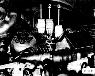
Models 325e, 325i, 325i CAT: Remove main relay -3- DME. so that no fuel is injected during the test. Additionally, the figure shows: -1- fuel pump relay; -2- lambda probe heating relay.
Attention: On model 325 \ without catalyst, the fuel pump relay is located on the relay socket -2-, the relay socket -1- is free.
Models 316i since September 19885, 318i since September 1987: remove the cover from the bulkhead under the wiper and pull the main relay located there from its socket. The main relay is located on the right side.
Remove all spark plugs. For this, special pliers are available, for example from the company HAZET 1849. But with these pliers, you can only take the metal sleeves of the tips.
Blow out the spark plug recesses in the cylinder head with compressed air and remove all spark plugs using a special spark plug wrench.
Crank the engine a few revolutions with the starter to remove carbon deposits.
Attention: The gearbox is in neutral position, the handbrake is applied.
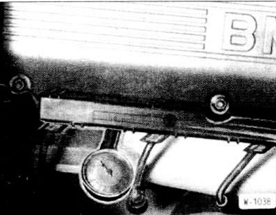
Connect the compression tester to the spark plug hole in accordance with its instruction manual.
Have an assistant press the gas pedal all the way down and keep the foot on the pedal in this position throughout the test.
Crank the engine about 8 revolutions until the gauge stops increasing.
Consistently check the compression in all cylinders and compare with the specified value.
Finally, screw in the spark plugs and connect the ignition wires.
Connect the connector of the transistor ignition switching unit.
Install a fuel pump relay or main relay. diesel engine
Model 324d: Push forward the high pressure fuel pump cut-off lever.
Model 324td: remove the main relay.
Disconnect the electrical wires from the glow plugs and unscrew the glow plugs with the appropriate key head.
Instead of glow plugs, screw in a compression tester.
After checking, screw in and tighten the glow plugs to 25 Nm. Pre-coat the threads of the candles with copper paste «CRC».
Connect the wires to the glow plugs with a tightening torque of 5 Nm.
Return the high pressure fuel pump cut-off lever to the rear position or insert the main relay.