



Table of contents: Removal ↓ Installation ↓
- Home
- BMW 3 Series
- E30
- Power unit
- M10/M20 engine
- Removal and installation the engine
Removal and installation the engine (BMW 3 Series E30)
The engine is removed without the gearbox, upwards. The intake and exhaust manifolds, as well as the carburetor and generator, remain on the engine. In no case should the engine be removed downwards with a mobile garage jack, as this can damage the engine.
Since some connections need to be removed from underneath the car, it needs to be lifted and placed on reliable stands. The front fenders need to be covered before installation work in the engine compartment.
Electrical wires, as well as vacuum and water hoses, may be routed differently in the engine compartment, depending on the year of manufacture and the composition of the equipment. Since it is impossible to provide a detailed description of each of the routing options, it is recommended to mark the wires and hoses when disconnecting them.
Remove the engine compartment hood (see section "Removal and installation the engine compartment hood").
Disconnect the wires from the battery.
Remove the gearbox (see section "Removal and installation the gearbox").
Lower the car.
Vehicles with power steering: remove the V-belt, remove the power steering pump and, without disconnecting the hoses, set aside.
Cars with air conditioning: unscrew the air conditioning compressor mount and set it aside with the connections connected.
Model 316: Remove the air filter (see section "Removal and installation the air filter").
Drain the coolant (see section "Replacing the coolant").
Remove the radiator (see section "Removal and installation the radiator").
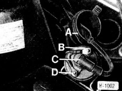
Remove the protective cap "A" from the ignition coil. Pull out the high-voltage wire "C" and unscrew the low-voltage wires "B" and "D". Cut the cable clamp in the shock absorber tunnel.
Disconnect the alternator connector.
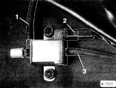
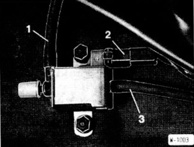
Disconnect connector "2" and vacuum hoses "1" and "3" from the electric shift valve.
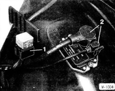
Lift the plastic protective cap. Remove the switching relay and disconnect connector "1".
Disconnect connector "2" of the transistor ignition switching unit.
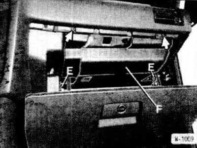
Open the glove box and unscrew the cover "F". To do this, turn the rear screw "E" 90° to the left, unscrew the front screws (arrows). Then detach the right side of the cover and pull out the cover.
Disconnect connectors "G" and "H" from the control unit.
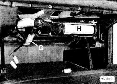
After this, remove the control unit wiring harness from the engine compartment.
Remove the throttle cable (see section "Adjusting the throttle cable").
If present, remove the Tempomat cable (speed stabilization).
Mark with tape and disconnect all vacuum hoses that go to the engine.
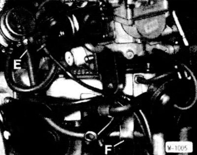
Model 316: Disconnect fuel hose "E" from the fuel pump and from the mount "F". First, loosen and move the clamp back.
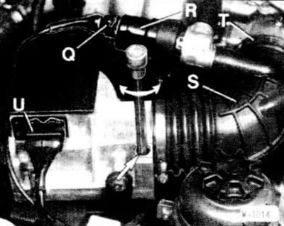
Disconnect the "U" connector from the air flow meter.
On the air flow meter, release and move the clamp back.
Unscrew the air flow meter bracket and remove the air filter housing together with the air flow meter.
Disconnect the fuel hoses and plug them to prevent fuel from leaking.
Remove the expansion tank of the cooling system. To do this, disconnect the two water and one ventilation hose, as well as the coolant level sensor connector and unscrew the two expansion tank mounting screws.
Disconnect the heating system hoses from the bulkhead, having first released and pulled back the clamps.
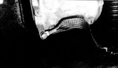
Unscrew the ground jumper from the oil pan.
If there are engine shock absorbers, unscrew and remove.
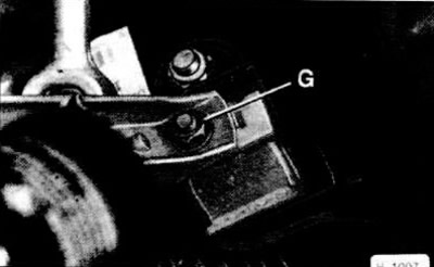
Release both engine mounts by unscrewing nuts "G".
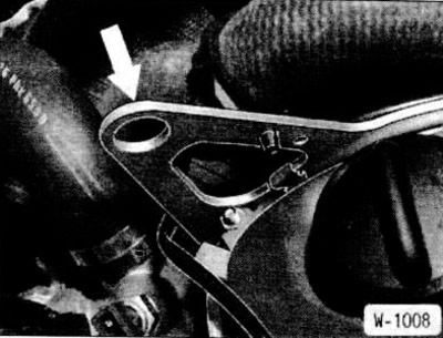
Hook the engine with a cable. To do this, pass the appropriate cable or chain through the engine lifting eyes (arrow). Raise the engine with a crane.
Check if all hoses and wires connecting the engine to the body have been removed. Then remove the engine.
Check the engine mounts, water, oil and fuel hoses for breaks or cracks and replace them if necessary.
Check the engine shock absorbers. To do this, hold the shock absorber in the working position and pull out and press the shock absorber rod. In this case, the shock absorber rod should move smoothly and with the same resistance throughout the entire working stroke. If there is a large oil leak, replace the shock absorber.
Check the ease of rotation of the crankshaft radial bearing and the clutch release bearing, as well as the ease of movement of the clutch fork.
Check the thickness and condition of the friction lining of the driven clutch disc.
Carefully insert the engine into the engine compartment. To avoid damage to the drive shaft, clutch and body, lower the engine very carefully.
Screw on the engine mount nuts without tightening them.
Raise the car.
Install the gearbox (see section "Removal and installation the gearbox").
Lower the car.
Push the engine to align it. Then tighten the engine mounts to 45 Nm.
If the engine shock absorbers were removed, insert and secure them.
Screw the ground jumper onto the oil pan.
Connect the heating system hoses to the bulkhead and secure with clamps.
Insert and secure the expansion tank of the cooling system. Connect the ventilation and water hoses. Connect the coolant level sensor connector.
Fuel injection engine: Check the air filter element, empty or replace if necessary. Secure the air hose with a clamp.
Install and adjust the throttle cable (see section "Adjusting the throttle cable").
Install the Tempomat system cable, if present.
Engine with fuel injection device: pull the wiring harness of the control unit into the passenger compartment and connect the connector to the control unit. Insert and screw the trim.
Connect both connectors of the transistor ignition system switching unit.
Insert the switching relay into the additional relay block. Connect the connector.
Connect the electrical wires to the electric shift valve. Connect the vacuum hoses "1" to the distributor and "3" to the throttle valve.
Connect the electrical wires to the ignition coil. Put the protective cap on the coil.
Connect the connector to the generator.
Install the radiator (see section "Removal and installation the radiator").
If removed, secure the air conditioning compressor and power steering pump, secure them. Apply and tighten the V-belt (see section "Replacing and tensioning the V-belt of the power steering pump").
Connect all electrical wires, vacuum, water and fuel hoses in accordance with the markings made during removal. Secure the hoses with clamps. Secure the wires with cable clamps.
Check the oil level in the engine and gearbox and top up if necessary.
Check the frost resistance of the coolant and add it if necessary (see section "Checking the coolant level").
Clean the air filter element or replace it if necessary.
Install the air filter (see section "Removal and installation the air filter").
Connect the wires to the battery.
Check the ignition timing and adjust if necessary (see section "Checking and adjusting the ignition timing").
Check and, if necessary, adjust idle speed parameters.
Warm up the engine to operating temperature, check the coolant level and the tightness of all hose connections.
Check valve clearances (see section "Checking and adjusting valve clearances").
Install the engine compartment hood (see section "Removal and installation the engine compartment hood").
Since some connections need to be removed from underneath the car, it needs to be lifted and placed on reliable stands. The front fenders need to be covered before installation work in the engine compartment.
Electrical wires, as well as vacuum and water hoses, may be routed differently in the engine compartment, depending on the year of manufacture and the composition of the equipment. Since it is impossible to provide a detailed description of each of the routing options, it is recommended to mark the wires and hoses when disconnecting them.
Removal
Remove the engine compartment hood (see section "Removal and installation the engine compartment hood").
Disconnect the wires from the battery.
Remove the gearbox (see section "Removal and installation the gearbox").
Lower the car.
Vehicles with power steering: remove the V-belt, remove the power steering pump and, without disconnecting the hoses, set aside.
Caution: If the hydraulic system has to be opened after installation (see section "Checking the oil level in the hydraulic power steering").
Cars with air conditioning: unscrew the air conditioning compressor mount and set it aside with the connections connected.
Caution: Do not open the cooling circuit under any circumstances.
Model 316: Remove the air filter (see section "Removal and installation the air filter").
Drain the coolant (see section "Replacing the coolant").
Remove the radiator (see section "Removal and installation the radiator").
Caution: If the water hoses are secured with clamps, cut the clamps and use screw clamps during installation.
Remove the protective cap "A" from the ignition coil. Pull out the high-voltage wire "C" and unscrew the low-voltage wires "B" and "D". Cut the cable clamp in the shock absorber tunnel.
Disconnect the alternator connector.
Disconnect connector "2" and vacuum hoses "1" and "3" from the electric shift valve.
Lift the plastic protective cap. Remove the switching relay and disconnect connector "1".
Disconnect connector "2" of the transistor ignition switching unit.
Open the glove box and unscrew the cover "F". To do this, turn the rear screw "E" 90° to the left, unscrew the front screws (arrows). Then detach the right side of the cover and pull out the cover.
Disconnect connectors "G" and "H" from the control unit.
After this, remove the control unit wiring harness from the engine compartment.
Remove the throttle cable (see section "Adjusting the throttle cable").
If present, remove the Tempomat cable (speed stabilization).
Mark with tape and disconnect all vacuum hoses that go to the engine.
Model 316: Disconnect fuel hose "E" from the fuel pump and from the mount "F". First, loosen and move the clamp back.
6-cylinder engine
Disconnect the "U" connector from the air flow meter.
On the air flow meter, release and move the clamp back.
Unscrew the air flow meter bracket and remove the air filter housing together with the air flow meter.
Disconnect the fuel hoses and plug them to prevent fuel from leaking.
Remove the expansion tank of the cooling system. To do this, disconnect the two water and one ventilation hose, as well as the coolant level sensor connector and unscrew the two expansion tank mounting screws.
Disconnect the heating system hoses from the bulkhead, having first released and pulled back the clamps.
Unscrew the ground jumper from the oil pan.
If there are engine shock absorbers, unscrew and remove.
Release both engine mounts by unscrewing nuts "G".
Hook the engine with a cable. To do this, pass the appropriate cable or chain through the engine lifting eyes (arrow). Raise the engine with a crane.
Check if all hoses and wires connecting the engine to the body have been removed. Then remove the engine.
Caution: To avoid damage to the body, handle the engine very carefully when removing it.
Installation
Check the engine mounts, water, oil and fuel hoses for breaks or cracks and replace them if necessary.
Check the engine shock absorbers. To do this, hold the shock absorber in the working position and pull out and press the shock absorber rod. In this case, the shock absorber rod should move smoothly and with the same resistance throughout the entire working stroke. If there is a large oil leak, replace the shock absorber.
Check the ease of rotation of the crankshaft radial bearing and the clutch release bearing, as well as the ease of movement of the clutch fork.
Check the thickness and condition of the friction lining of the driven clutch disc.
Carefully insert the engine into the engine compartment. To avoid damage to the drive shaft, clutch and body, lower the engine very carefully.
Screw on the engine mount nuts without tightening them.
Raise the car.
Install the gearbox (see section "Removal and installation the gearbox").
Lower the car.
Push the engine to align it. Then tighten the engine mounts to 45 Nm.
If the engine shock absorbers were removed, insert and secure them.
Screw the ground jumper onto the oil pan.
Connect the heating system hoses to the bulkhead and secure with clamps.
Insert and secure the expansion tank of the cooling system. Connect the ventilation and water hoses. Connect the coolant level sensor connector.
Fuel injection engine: Check the air filter element, empty or replace if necessary. Secure the air hose with a clamp.
Install and adjust the throttle cable (see section "Adjusting the throttle cable").
Install the Tempomat system cable, if present.
Engine with fuel injection device: pull the wiring harness of the control unit into the passenger compartment and connect the connector to the control unit. Insert and screw the trim.
Connect both connectors of the transistor ignition system switching unit.
Insert the switching relay into the additional relay block. Connect the connector.
Connect the electrical wires to the electric shift valve. Connect the vacuum hoses "1" to the distributor and "3" to the throttle valve.
Connect the electrical wires to the ignition coil. Put the protective cap on the coil.
Connect the connector to the generator.
Install the radiator (see section "Removal and installation the radiator").
If removed, secure the air conditioning compressor and power steering pump, secure them. Apply and tighten the V-belt (see section "Replacing and tensioning the V-belt of the power steering pump").
Connect all electrical wires, vacuum, water and fuel hoses in accordance with the markings made during removal. Secure the hoses with clamps. Secure the wires with cable clamps.
Check the oil level in the engine and gearbox and top up if necessary.
Check the frost resistance of the coolant and add it if necessary (see section "Checking the coolant level").
Clean the air filter element or replace it if necessary.
Install the air filter (see section "Removal and installation the air filter").
Connect the wires to the battery.
Check the ignition timing and adjust if necessary (see section "Checking and adjusting the ignition timing").
Check and, if necessary, adjust idle speed parameters.
Warm up the engine to operating temperature, check the coolant level and the tightness of all hose connections.
Check valve clearances (see section "Checking and adjusting valve clearances").
Install the engine compartment hood (see section "Removal and installation the engine compartment hood").
This article is available at russian, bulgarian, belarusian, ukrainian, serbian, croatian, romanian, polish, slovak, hungarian
Article verified: Polikarpov Saveliy
Share information:
Previous articles
БМВ E30: M10/M20 engine
Next articles
Similar articles on other types of BMW cars:
Removal and installation the engine BMW 5 Series E12 (1972-1981)
Removal and installation the engine BMW 5 Series E34 (1988-1996)
Engine — removal and installation BMW 7 Series E32 (1986-1994)
Removal and installation the engine BMW 7 Series E38 (1994-2001)
Removal and installation the engine assembly BMW X3 E83 (2003-2010)
Removal and installation the engine BMW X5 E53 (1999-2006)
Removal and installation the engine BMW 5 Series E12 (1972-1981)
Removal and installation the engine BMW 5 Series E34 (1988-1996)
Engine — removal and installation BMW 7 Series E32 (1986-1994)
Removal and installation the engine BMW 7 Series E38 (1994-2001)
Removal and installation the engine assembly BMW X3 E83 (2003-2010)
Removal and installation the engine BMW X5 E53 (1999-2006)
Link in different formats to this page
Visitor comments
No comments yet
- General information
- Manual
- Maintenance
- Power unit
- Engine repair
- Cooling system
- Power system (gasoline)
- Injection system (gasoline)
- Fuel system (diesel)
- Exhaust system
- Ignition system
- Charge and launch systems
- Transmission
- Car gearbox
- Clutch and drive shafts
- Chassis
- Brake system
- Suspension front and rear
- Steering
- Body
- Body care and repair
- Exterior
- Interior
- Electrical equipment
- Troubleshooting
- Lighting and signaling
- Equipment and devices
- Heater and air conditioner
- Electrical circuits
- General information
- Manual
- Repair on the road
- Weekly checks
- Maintenance
- Troubleshooting
- Power unit
- 4 cylinder engines
- 6 cylinder engines
- Engine overhaul
- Cooling and heating
- Fuel and exhaust system
- Starting and charging system
- Ignition system
- Transmission
- Clutch
- Mechanical gearbox
- Automatic gearbox
- Cardan and drive shafts
- Chassis
- Brake system
- Wheel suspension
- Steering
- Body
- Exterior
- Interior
- Electrical equipment
- Equipment and devices
- Electrical circuits
- General information
- Maintenance
- Power unit
- Engine repair
- Cooling system
- Ignition system
- Supply system
- Fuel injection system
- Exhaust system
- Transmission
- Clutch
- Car gearbox
- Front and rear axle
- Chassis
- Steering
- Brake system
- Body
- Exterior
- Interior
- Electrical equipment
- Heating system
- Equipment and devices
- Power devices
- Electrical circuits
- Power unit
- M10/M20 engine
- M40 engine
- Ignition system
- Lubrication system
- Cooling system
- Supply system
- Fuel injection
- Exhaust system
- Transmission
- Clutch
- Manual gearbox
- Front axle
- Rear axle
- Chassis
- Steering
- Brake system
- Body
- Exterior
- Interior
- Electrical equipment
- Heating system
- Equipment and devices
- Electrical circuits
- General information
- Specifications
- Operation and maintenance
- 4-cylinder engine
- Engine repair
- Cooling and lubrication system
- Supply system
- Ignition system
- 6-cylinder engine
- Engine repair
- Cooling and lubrication system
- Supply system
- Fuel injection system
- Ignition system
- Transmission
- Clutch
- 4-speed manual gearbox
- 5-speed manual gearbox
- Automatic gearbox
- Cardan and rear axle
- Chassis
- Steering
- Front suspension
- Rear suspension
- Brake system
- Electrical equipment
- Equipment and devices
- Electrical circuits