



Removal and installation the cylinder head
Attention:
- Replace the cylinder head bolts. Do not wash off the coating from the bolts. There should be no coolant, water or engine oil in the blind holes.
- Protect the generator from contamination with engine oil and coolant. Cover the generator.
- The hoses must be dry and free of grease.
- Inflatable air hoses with push-in connection (pay attention when installing).
- If no work has been carried out on the cylinder block that causes a change in the piston crown protrusion, then a new cylinder head gasket with the same thickness marking should be used (number of marking holes).
1. Disconnect the negative battery cable.
2. Remove the intake manifold.
3. Remove the injectors.
4. Remove the Common Rail system ramp.
5. Remove the cylinder head cover.
6. Drain the coolant.
7. Remove the EGR radiator.
8. Remove both camshafts.
9. Remove all HVA components and roller tappet levers.
10. Remove all glow plugs.
11. Loosen the exhaust gas turbocharger mounting bolts and remove it.
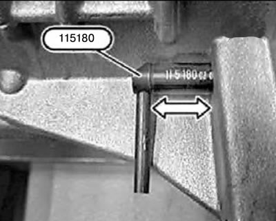
12. Turn the crankshaft by the central bolt in the direction of rotation until the piston of the first cylinder is set to the "TDC position".
13. Lock the crankshaft at TDC using locking tool 115180.
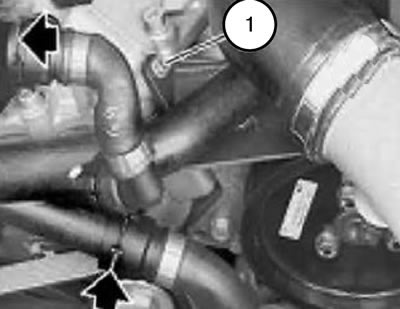
14. Unscrew the bolt (1).
15. The second fastening screw is located at the end of the return pipe.
Note: This screw must also be removed.
16. Release the clamps and disconnect the cooling system hoses.
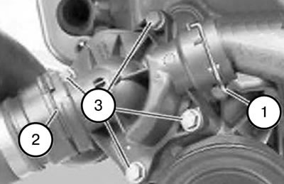
17. Pull back the clamps (1 and 2).
18. Disconnect the return pipe and cooling system hoses.
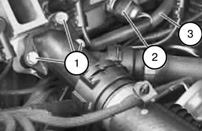
19. Remove the fasteners (1).
20. Lift the coolant adapter flange.
Note: When installing, it is necessary to replace the seal.
21. Disconnect the connector (2).
22. Disconnect the return fuel line (3),
23. Disconnect the temperature sensor connector (2).
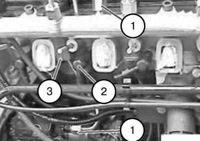
24. Unscrew the union nuts (1) using tool 135020.
Tightening torque: 23 Nm.
25. Disconnect all connectors (2).
26. Remove the rubber-metal hinge (3).
Note: When installing, please ensure that the rubber-to-metal hinge is installed correctly.
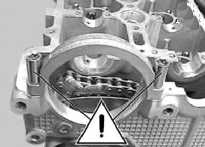
Caution: These bolts must not be removed.
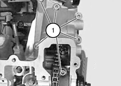
27. Unscrew the threaded plug (1) on the timing belt cover.
Note: One bolt is located in the cylinder head.
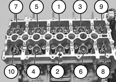
28. Unscrew the cylinder head mounting bolts from the edges to the middle in sequence 10...1.
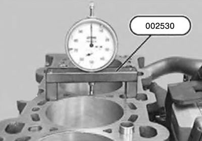
29. If work has been carried out on the crank drive or pistons, it is necessary to re-determine the repair thickness of the sealing gasket.
1) Measure the protrusion of the piston bottom relative to the plane of the cylinder block:
2) Install the dial indicator with measuring block, device 002530, on the cleaned sealing surface of the cylinder head and set it to the zero mark with pre-tension.
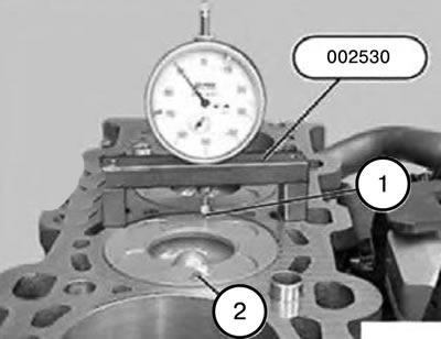
3) Clean the piston crowns at the measurement points (1 and 2).
4) Place the dial indicator on the cleaned piston at the measurement point (1) and, by turning the crankshaft, determine the highest point.
5) Measure and record the bottom protrusion at measurement points (1 and 2) for all 4 pistons.
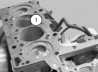
- Piston bottom protrusion 0.72-0.83 mm: Install a single hole sealing gasket.
- Piston bottom protrusion is greater than 0.83-0.93 mm: Install a two-hole sealing gasket.
- Piston bottom protrusion is greater than 0.93-1.04 mm: Install a three-hole sealing gasket.
30. Check the centering bushings (1) for damage and correct installation.
31. Install a new cylinder head gasket of a predetermined thickness (number of marking holes).
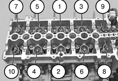
32. Install the cylinder head and tighten it with new mounting bolts (lightly oiling them) in sequence 1...10.
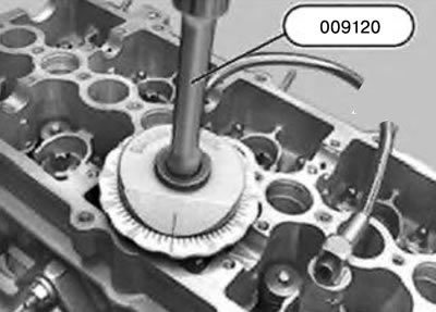
Note: Use tool 009120 to tighten to the specified angle.
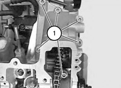
33. Insert and tighten the bolts.
34. Assemble the engine.