
Removal and installation camshafts
1. Remove the vacuum pump.
2. Remove the cylinder head cover.
3. Turn the engine crankshaft using the central bolt.
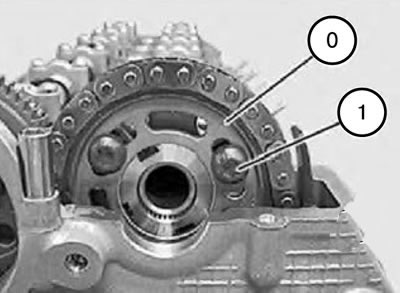
Note: The intake camshaft lobes of cylinder 1 face downwards.
4. Unscrew the bolt (1).
Note: First, you need to unscrew the bolt (1), since it will be inaccessible when in the TDC position.
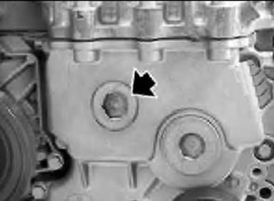
5. Unscrew the threaded plug on the lower timing belt cover.
Caution: The piston must not be in the TDC position.
6. Turn the engine back by 45° using the crankshaft.
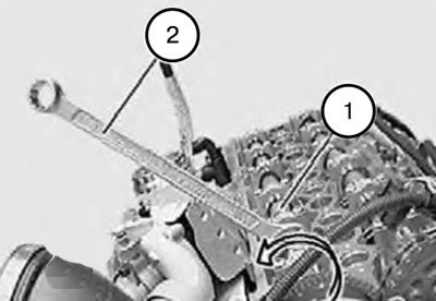
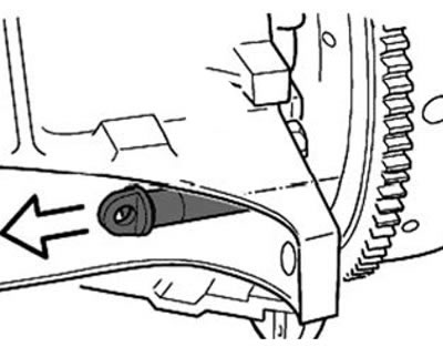
7. Turn the exhaust camshaft by the hexagon in the direction indicated by the arrow.
Note: The hydraulic chain tensioner can be locked in this position using tool 113340.
Note: When the intake or exhaust camshaft rotates, the hydraulic chain tensioner is retracted again.
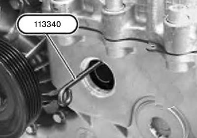
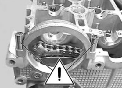
8. Lock the hydraulic chain tensioner using tool 113340.
Note: If the sprocket is removed without first locking the hydraulic chain tensioner, the tensioner piston may slip out, making reinstallation a very labor-intensive operation.
9. Remove the protective cover in the direction indicated by the arrow.
Note: When installing, it is necessary to put the protective cover back on, lightly lubricating it.
10. Turn the engine by the crankshaft using tool 116480.
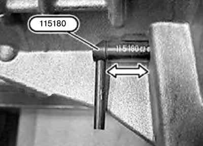
11. Lock the crankshaft by the flywheel using tool 115180.
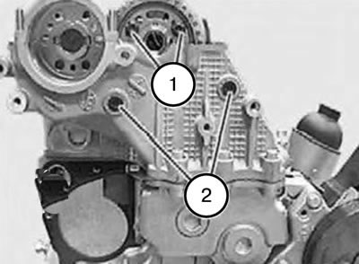
12. Unscrew the bolt (1) on the sprocket.
13. Unscrew the pin (2) of the chain guide hinge.
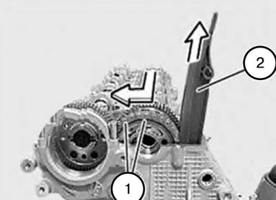
14. Loosen the fastening of the sprocket (1) of the intake camshaft in the direction indicated by the arrow.
15. Release the guide (2) from the mount and remove it in the direction indicated by the arrow.
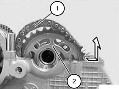
16. Release the sprocket (2) in the direction indicated by the arrow to the right of the chain (3) and remove it with an upward movement.

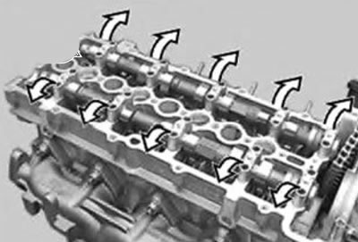
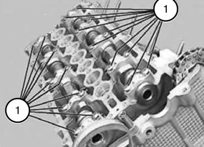
17. Evenly, in several half-turn steps, unscrew the bolts (1) securing the camshaft bearing caps from the edges to the middle.
Note: The figure shows M 47 TU.
18. Remove the bearing caps and take out the camshafts.
Note: All bearing caps are marked.
Note. Pushrod levers that have been used in service can only be used for the same camshaft cams.
Caution: These bolts must not be removed.
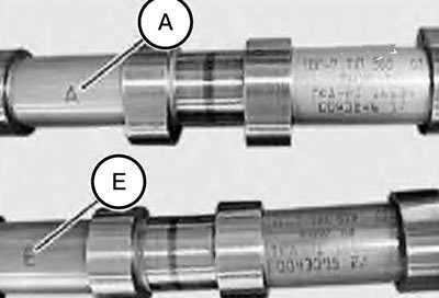
Note:
- E - Intake camshaft.
- A - Exhaust camshaft.
19. Place the camshafts.
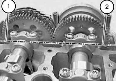
Note:
- Position (1) of the intake camshaft sprocket close to the cylinder head.
- Position (2) of the exhaust camshaft sprocket close to the cylinder head.
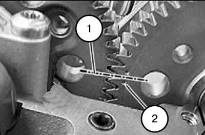
Note: The marking (1) on the intake valve camshaft must be located between the markings (2) on the exhaust valve camshaft.
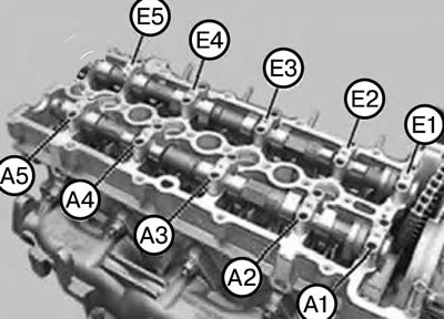
Note:
- The intake camshaft bearing caps are marked E1-E5 on the exhaust side.
- The exhaust camshaft bearing caps are marked A1 - A5 on the exhaust side.
Note:
- E - Intake camshaft.
- A - Exhaust camshaft.
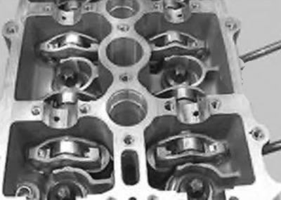
20. Install the bearing caps.
Note: The image shows M47.
21. Insert and tighten all bolts (1).
22. Evenly, in several half-turn steps, tighten the camshaft bearing cap bolts from the middle to the edges.
Note: The figure shows M 47.
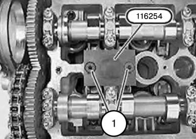
23. Secure tool 116254 to the cylinder head with bolts (1).
24. Check the axial clearance of the intake camshaft.
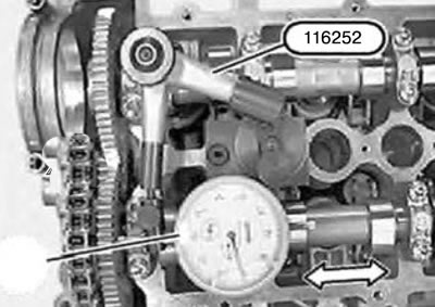
25. Install device 116252 with a pointer indicator.
Note: The sequence of actions is identical for the exhaust camshaft.
26. Adjust the valve timing.
27. Assemble the engine.