
- Home
- BMW 7 Series
- E32
- Power unit
- Engine overhaul
- Camshaft(s) — Removal and Installation
Camshaft(s) — Removal and Installation (BMW 7 Series E32)
M30 Series Engine Camshaft - Removal and Installation
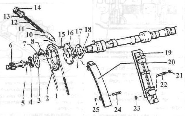
Mounting elements of the camshaft of the M30 series engine
1 — chain;
2 - asterisk;
3 — lock washer;
4 - nut;
5 - compaction;
6 - gear;
7 — bolt;
8 - lock washer;
9 — pin;
10 — plunger;
11 - ball;
12 — spring;
13 - compaction;
14 — plug;
15 — thrust ring;
16 — sprocket flange;
17 - thrust plate;
18 - spring washer;
19 — damper bar;
20 — tensioner bar;
21 - washer;
22 — finger;
23 - lock washer;
24 — finger;
25 - lock washer.
Removal
Remove the cylinder head and place it on two wooden slats.
Remove the oil line.
Set the valve clearances of all valves to maximum.
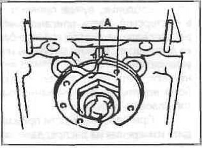
Set the camshaft to the position shown in the figure.
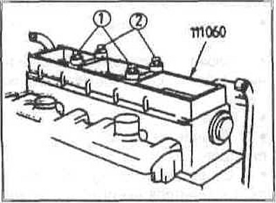
Install the pressure frame, pressing it with bolts (1) and (2). At the same time, move the exhaust rocker arms of the second and fourth cylinders forward by 7 mm.
Loosen the thrust plate bolts and carefully remove the camshaft with flange and thrust plate from the cylinder head. Remove the rocker arm retaining rings from the shaft. To do this, move the thrust ring aside and remove the burrs.
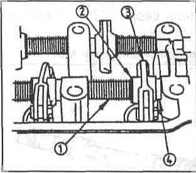
1 - spring;
2 - adjusting washer;
3 — rocker arm;
4 - thrust ring.
Remove the rocker arm shaft retaining bolts and install the rocker arm shaft puller.
After removing the axles, remove the rocker arms, thrust rings and springs.
Installation
Installation is carried out in reverse order.
Camshaft of the M52 series engine - removal and installation
Since this operation requires a special device, it is better to carry it out in a workshop. Here we describe how to remove the camshaft on a removed cylinder head. You can also work on an installed head, but you need to do some preliminary work up to unscrewing the cylinder head bolts.
If necessary, take measurements on the camshaft: axial clearance should be 0.15-0.33 mm, radial clearance 0.02-0.054 mm.
Loosen and remove all bearing cap bolts.
Removal
Remove the cylinder head. Unscrew the studs.
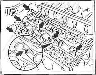
A special device is required to remove the camshaft. Its purpose is to hold all the camshaft bearings in their installation positions when the bearing shells are removed. The instructions apply to both camshafts, the order in which they are removed does not matter.
Remove the spark plugs.
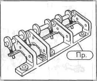
Install the fixture and secure it in the spark plug holes of the first and fourth cylinders.
Fix the bearing caps by turning the eccentric shaft of the device.
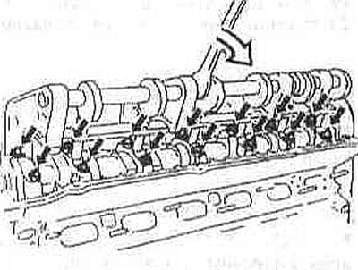
Loosen and remove all bearing cap bolts.
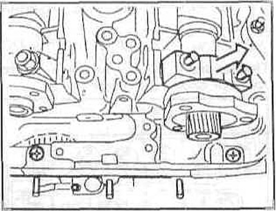
Caution: Center the first camshaft bearing cap for the intake valves using the installation sleeves. To prevent the camshaft from being tilted, unscrew the first bearing cap bolts.
Loosen the fixture and remove it.
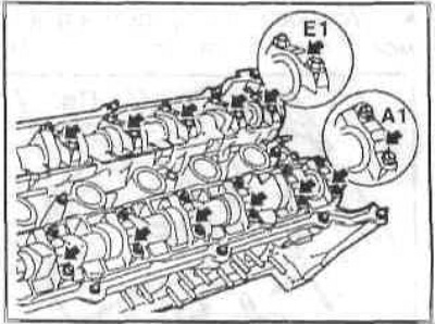
Remove the bearing caps and camshaft. Arrange the bearing caps in order so that they will be installed in their original positions. The bearing caps for the exhaust camshaft are marked with numbers from A1 to A7, and for the intake camshaft - from E1 to E7.
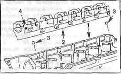
If necessary (for example, when removing valves), then the entire bearing strip (2) with valve tappets is removed. Pay attention to the centering bushings. The bearing strips in place (4) are marked with the letter A for the outlet side and the letter E for the inlet side.

Caution: The valve lifters may slide down out of the bearing plate if not secured. Specialist workshops use suction cups that fit over the lifters to prevent them from falling out. Mark the valve lifters. They will need to be reinstalled if removed.
Caution: Removed tappets must not be kept upside down for more than 10 minutes, otherwise they will fill with engine oil slowly and automatic valve clearance compensation will not occur.
Installation
Note: If the camshaft has been removed, the following should be noted: the hydraulic valve lifters expand without the load from the camshaft and need some time after installation to compress again. Because of this, the valves can open further than determined by the position of the camshaft and come into contact with the piston. In this regard, it is necessary to wait a certain time between installing the camshaft and installing the cylinder head: at +20°C (room temperature) — 4 minutes, at +10°C — 11 minutes. After installing the cylinder head, you need to wait another 30 minutes until the engine can be turned.
Note: If the camshaft was removed with the cylinder head installed, you need to turn the crankshaft approximately 30° in the normal direction of rotation by the hexagon on the pulley through the TDC position. Thanks to this, the piston will not be in the highest position, and the valves will not hit it. Install the camshaft and wait the time specified above. After this, you need to return the crankshaft to the TDC position and install the drive chain.
Check the valve lifters for wear (scratches, dents) and replace them if necessary.
Lubricate the camshaft bearings and insert the camshafts so that the ends of the intake and exhaust cams of the first cylinder are facing each other.
Insert the bearing plate with the valve lifters installed into the cylinder head. The centering bushings must be in place.
Insert the bearing shells in accordance with the marks made earlier into the same places from which they were removed.
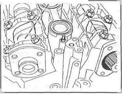
Install the fixture and secure the bearing caps and shells.
Tighten the bearing cap bolts to 15 Nm.
Release the tool and remove it. Screw in the spark plugs.
Install the cylinder head.
Diesel engine camshaft series M51 - removal and installation
Since these operations require a special device, it is recommended to carry out the work in a workshop. The camshaft can be removed both with the cylinder head installed and with it removed. Here we describe how to remove the camshaft from an already removed head. You can also work on an installed head, but you need to carry out preliminary operations up to unscrewing the cylinder head bolts, following the instructions in the corresponding section.
If necessary, take measurements on the camshaft: the radial clearance should be 0.04-0.081 mm, the axial clearance 0.15-0.33 mm.
Removal
Remove the cylinder head.
A special device is required to remove the camshaft. Its purpose is to hold all the camshaft bearings in the installation position while removing the bearing shells. Install the device and secure it with the valve cover bolts.
Turn the eccentric shaft of the device to press the bearing caps.
Remove all bearing cap bolts.
Loosen the fixture and remove it.
Remove the bearing caps and camshaft. The bearing caps are marked with numbers 1 through 7 on the exhaust side.
If necessary, for example when removing valves, then the valve tappets should be removed. In a specialized workshop, suction cups are used, which are installed on top of the tappets to pull them out. After removal, the tappets must be installed in their original places.
Caution: Removed tappets should not be left upside down for more than 10 minutes, otherwise they will fill with engine oil slowly and automatic valve clearance compensation will not occur.
Installation
Check the valve lifters for wear (scratches) and replace them if necessary. Install them in the same places as before removal.
Lubricate the camshaft bearings and insert the camshaft so that the ends of the intake and exhaust cams of the first cylinder are facing upward.
Insert the bearing shells according to the numbers in the same positions as before removal.
Place the fixture and press the bearing caps with the liners.
Tighten the bearing cap bolts evenly in a criss-cross pattern, working from the outside in ½ turn increments, to a torque of 15 Nm.
Release the device and remove it.
Install the cylinder head.
Note: If the camshaft has been removed, the following should be noted: the hydraulic valve lifters expand without the load from the camshaft and need some time after installation to compress again. Because of this, the valves can open further than determined by the position of the camshaft and come into contact with the piston. In this regard, it is necessary to wait a certain time between installing the camshaft and installing the cylinder head: at +20°C (room temperature) — 4 minutes, at +10°C — 11 minutes. After installing the cylinder head, you need to wait another 30 minutes until it becomes possible to turn the engine.
Note: If the camshaft was removed with the cylinder head installed, the crankshaft must be turned approximately 30° in the normal direction of rotation by the hexagon on the pulley through the TDC position. This will prevent the piston from being in the highest position and the valves from hitting it. Install the camshaft and wait the time specified above. After this, the crankshaft must be returned to the TDC position and the drive chain must be installed.
M70 Series Engine Camshaft - Removal and Installation
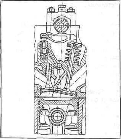
Installation position of the camshaft
Removal
If necessary, take measurements on the camshaft: the radial clearance should be 0.04-0.081 mm, the axial clearance 0.15-0.33 mm.
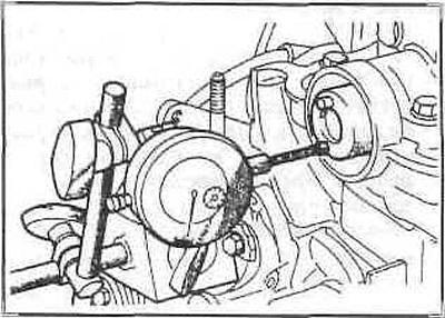
Measuring axial clearance of the camshaft
Remove the cylinder head. Remove the spark plugs. Remove the oil distribution pipe. With the corresponding camshaft cams facing up, remove the levers. Place the levers so that they can be installed in their original position.
Remove the camshaft bearing caps and take out the shafts. Take out the hydraulic tappets and lay them out in a vertical installation position. After removing the tappets, you need to install them in their original places.
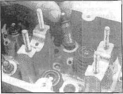
Installation
The camshaft installation is carried out in the following sequence:, reverse removal taking into account the recommendations given in previous section.
(The article was copied from an online resource: «BMWMAN.ru»)
This article is available at russian, bulgarian, belarusian, ukrainian, serbian, croatian, romanian, polish, slovak, hungarian
Article verified: Sevastyanov Nikolay
Share information:
Previous articles
БМВ E32: Engine overhaul
Next articles
Similar articles on other types of BMW cars:
Removal and installation the camshaft BMW 3 Series E21 (1975-1983)
Removal and installation the camshaft BMW 3 Series E30 (1982-1994)
Removal and installation the camshaft BMW 5 Series E34 (1988-1996)
Removal and installation the camshaft — model 520d (engine M47) only BMW 5 Series E39 (1995-2003)
Pistons — removal and installation BMW X3 E83 (2003-2010)
Removal and installation the engine BMW X5 E53 (1999-2006)
Removal and installation the camshaft BMW 3 Series E21 (1975-1983)
Removal and installation the camshaft BMW 3 Series E30 (1982-1994)
Removal and installation the camshaft BMW 5 Series E34 (1988-1996)
Removal and installation the camshaft — model 520d (engine M47) only BMW 5 Series E39 (1995-2003)
Pistons — removal and installation BMW X3 E83 (2003-2010)
Removal and installation the engine BMW X5 E53 (1999-2006)
Link in different formats to this page
Visitor comments
No comments yet
- General information
- Introduction to guide
- Manual
- Maintenance
- Power unit
- Engine M60/1, M60/2 (petrol)
- M62 engine (petrol)
- M57 engine (diesel)
- M67 engine (diesel)
- Cooling system
- Fuel system (petrol)
- Fuel system (diesel)
- Exhaust system
- Ignition and control systems
- Charge and launch systems
- Transmission
- Clutch
- Mechanical gearbox
- Automatic gearbox
- Cardan and drive shafts
- Chassis
- Brake system
- Front suspension
- Rear suspension
- Steering
- Body
- Exterior
- Interior
- Electrical equipment
- Equipment and devices
- Lighting
- Heating and air conditioning
- Electrical circuits
- General information
- Care and maintenance
- Power unit
- Minor engine repair
- Engine overhaul
- Lubrication system
- Cooling system
- Ignition system
- Supply system
- Injection system (petrol)
- Injection system (diesel)
- Exhaust system
- Transmission
- Clutch
- Manual gearbox
- Automatic gearbox
- Cardan gear
- Rear axle and shafts
- Chassis
- Front suspension
- Rear suspension
- Steering
- Wheels and tires
- Brake system
- Body
- Body elements
- Electrical equipment
- Equipment and devices
- Electrical circuits