
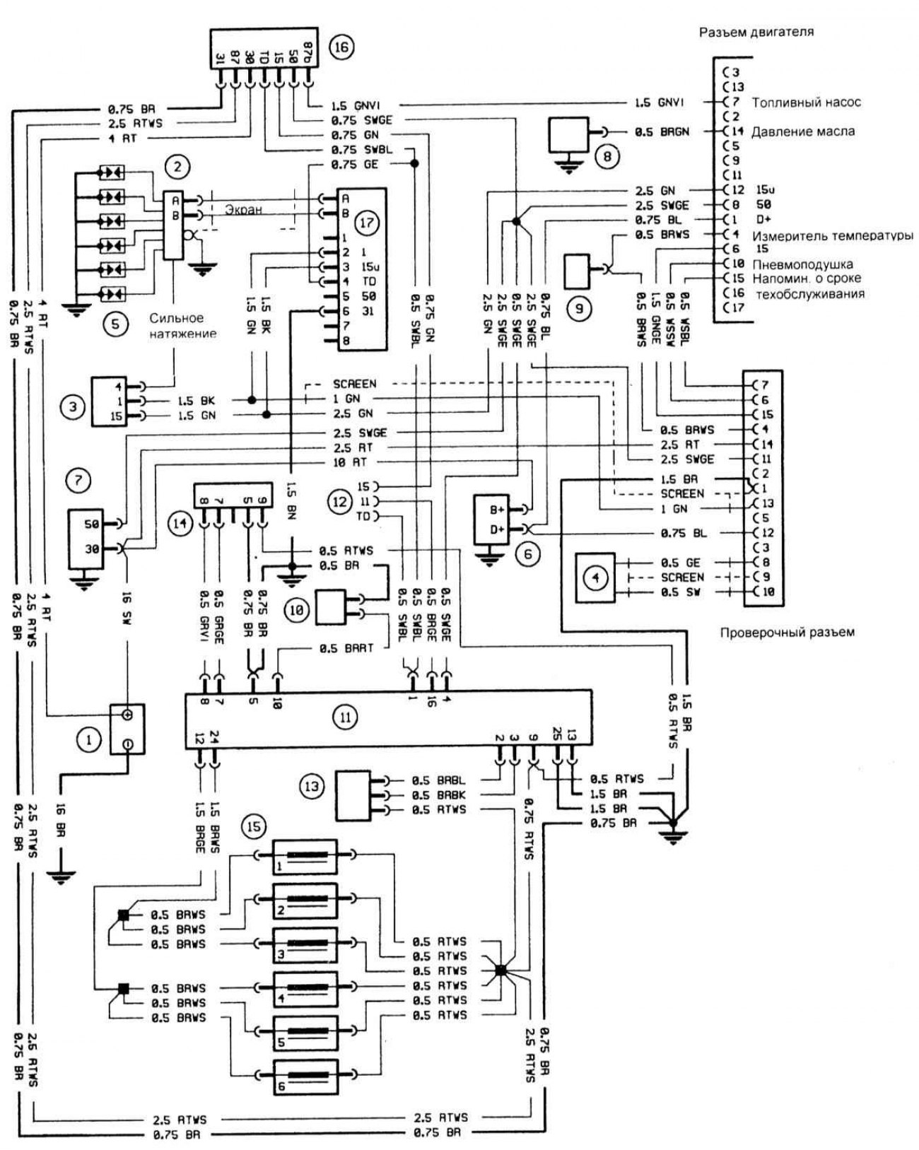
Schematic diagram of a typical L-Jetronic system
Open large image in new tab »
1 - Battery
2 — Ignition distributor
3 - Ignition coil
4 — Position sensor
5 - Spark plugs
6 — Generator
7 — Starter
8 — Oil pressure sensor
9 - Temperature transmitter
10 — Coolant temperature sensor
11 — Fuel injection control unit
12 — Wiring connector
13 — Throttle switch
14 — Air flow sensor
15 — Fuel injectors
16 — Fuel pump relay
17 — Ignition module
[1 - Engine connector
2 - Fuel pump
3 - Oil pressure
4 - Temperature meter
5 - Air spring
6 — Maintenance due date reminder
7 — Test connector
8 — Screen
9 - Strong tension]
You can read the original on the website: BMWman.ru