
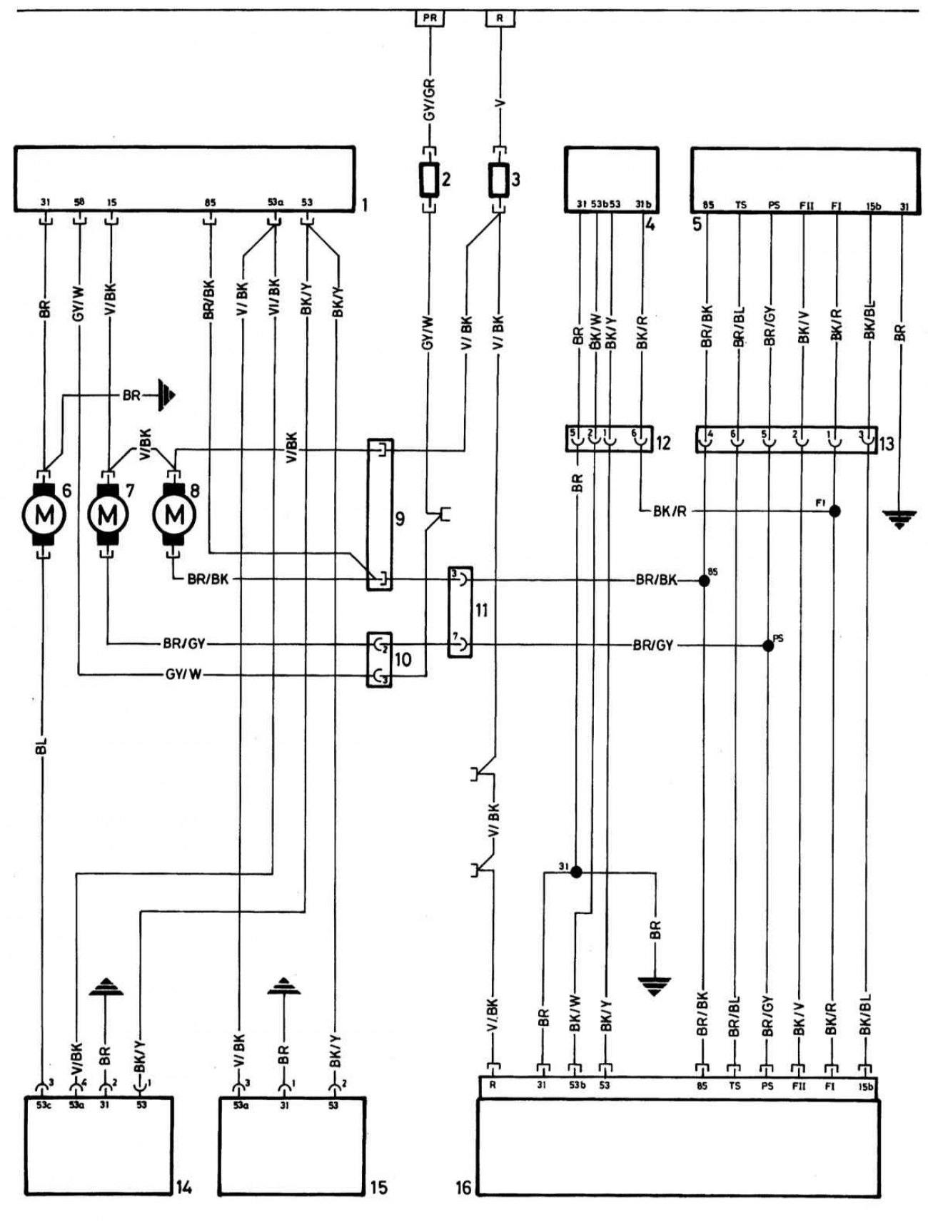
Schematic diagram of a typical headlamp washer system
Open large image in new tab »
1 — Headlight wiper control unit
2 - Fuse - night lighting, rear and parking lights
3 — Fuse - horns, windscreen wiper/washer control unit and headlamp wipers
4 — Motor - windshield wipers
5 - Windscreen wiper switch
6 — Pump - headlight wiper system
7 — Pump - supply of cleaning liquid
8 — Pump - windshield washer system
9 — Plug - headlight wiper wire to front section 1 (washer fluid supply pump)
10 — Plug - headlight wiper wire to front section 2 (headlight wiper plug)
11 - Plug - center section to front section (7 contacts)
12 — Windscreen wiper motor plug
13 - Plug - center section to windshield wiper switch
14 — Motor - windshield wipers
15 — Left headlight wiper motor
16 — Windscreen washer/wiper switch control unit