
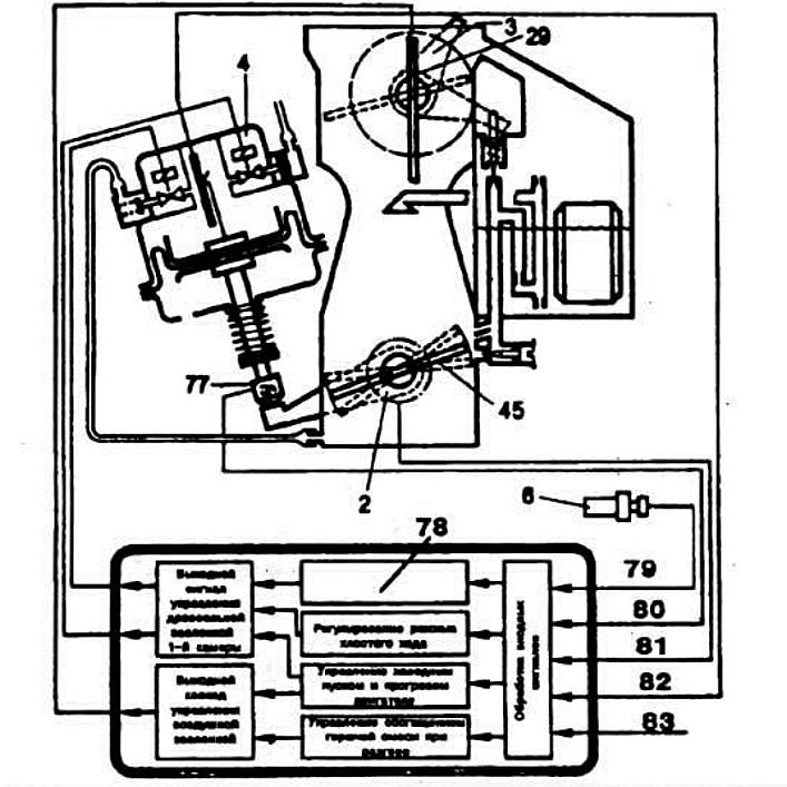
Functional diagram of the Ecotronic system controller:
2 — 1st chamber throttle potentiometer; 3 — air damper servo drive; 4 — 1st chamber throttle valve servo drive; 6 - coolant temperature sensor; 29 — air damper; 45 — 1st chamber throttle valve; 77 - Idle switch; 78 — control of fuel supply cut-off during engine braking and engine stop; 79 — signal "Coolant temperature"; 80 — signal "Idle switch position"; 81 — signal "Angular position of the throttle valve of the 1st chamber"; 82 — signal "Position of the throttle valve servo pusher of the 1st chamber"; 83 — signal "Engine speed".
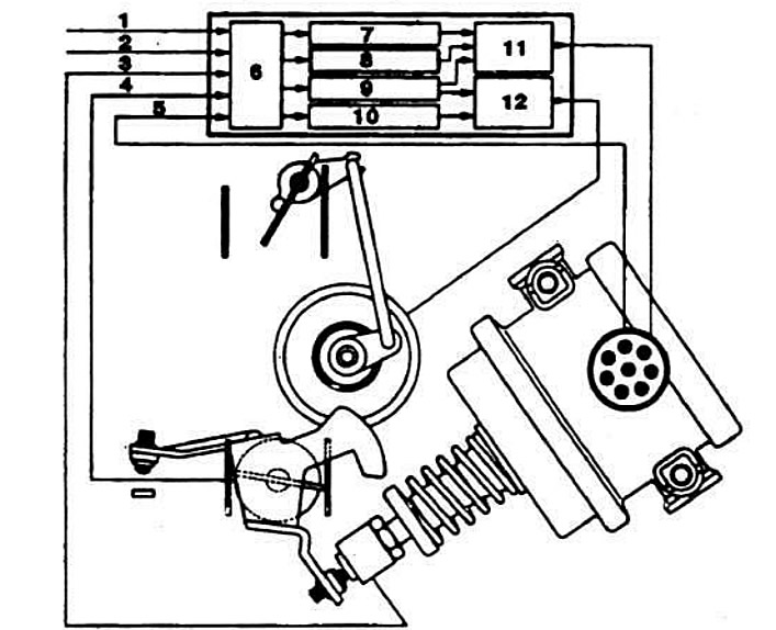
Functional diagram of the Ecotronic system controller:
1 - "Coolant temperature" signal; 2 — signal "Engine speed"; 3 — signal "Idle switch position"; 4 — signal "Angular position of the throttle valve of the 1st chamber"; 5 — signal "Position of the throttle valve servo pusher of the 1st chamber"; 6 - input signal processing; 7 — control of fuel supply cut-off during engine braking and engine stop; 8 - idle speed control; 9 — control of cold start and engine warm-up; 10 - control of enrichment of the combustible mixture during acceleration; 11 — output stage of throttle valve control of the 1st chamber; 12 — air damper control output stage.