
- Home
- BMW 5 Series
- E12
- Power unit
- Ecotronic power supply system
- Appearance and description of the 2BE carburetor
Appearance and description of the 2BE carburetor (BMW 5 Series E12)
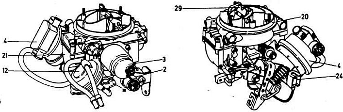
External appearance of the 2BE carburetor:
2 — 1st chamber throttle potentiometer; 3 — air damper servo drive; 4 — 1st chamber throttle valve servo drive; 12 — pneumatic drive of the throttle valve of the 2nd chamber; 20 — carburetor cover; 21 — carburetor body; 22 — throttle body; 24 — idle speed switch connector; 29 — air damper.
Features of the device
The carburetor is an emulsion type, two-chamber, with sequential opening of the throttle valves. It is characterized by a compact design and low height. Each chamber has a float chamber and a separate float, as a result of which the carburetor is insensitive to the action of centrifugal force that occurs during turns, and inertia during sharp acceleration and braking. The carburetor can be installed along the longitudinal or transverse axis of the car. Due to the use of flooded jets (i.e. they are located below the fuel level) and the special arrangement of the fuel channels 8 in the carburetor completely eliminates the possibility of gasoline vapor formation. The carburetor has two independent economizers with flooded jets. This ensures optimal adaptation of the carburetor to all engine operating modes. Below is a description of the design and operating principle of the main parts of the carburetor.
Throttle body (pos. 22 see drawings)
The throttle body contains the throttle valve axes, each of which rotates in two bearings, levers, return springs and throttle valve axis stops, as well as an idle mixture quality (composition) adjusting screw. Emulsion channels of the idle system, channels of the transition systems of the 1st and 2nd chambers and openings for the shut-off (blocking) the valves of the 2nd chamber are made directly in the body of the throttle valve housing. The holes for vacuum selection for the vacuum corrector of the ignition distributor sensor and for the electropneumatic drive of the throttle valve of the 1st chamber are connected to them by hoses.
In the opening zone of the throttle valve of the 1st chamber, a hole is drilled to select vacuum for controlling the air valve of the engine braking system.
Carburetor body (pos. 21)
In addition to two float chambers, diffusers and corresponding holes, the carburetor body houses the fuel jet of the 2nd chamber transition system. The connecting tube of the 2nd chamber control system is pressed into the carburetor body. The diaphragm-type pneumatic drive of the 2nd chamber throttle valve and the servo drives of the air damper and throttle valve of the 1st chamber are installed on the body.
Throttle valve potentiometer 1st chamber (pos.2)
The potentiometer is designed to adjust the position and track the movements of the throttle valve of the first chamber. Information from the potentiometer is sent to the controller. The potentiometer rotates around its axis and has a built-in return spring to compensate for the gap. In order to take into account changes due to manufacturing tolerances, the potentiometer is mechanically connected to the axis of the throttle valve of the first chamber.
Air damper servo drive (pos. 3)
The air damper servo is controlled by the controller and determines the composition of the fuel-air mixture during cold start, warm-up, acceleration and at partial engine load. Enrichment of the combustible mixture is ensured by a pressure drop due to the closing of the air damper and the movement of the idle air jet needle depending on the position of the air damper (this reduces the flow area of the idle air jet).
Adjusting the air-fuel mixture (and depending on the amount of incoming air and the position of the air damper) depends mainly on the available moment in the area of the air damper, the axis of which is offset, so its servo drive works as a torque motor. The torque produced by the motor in turn depends on the angular position of the air damper and on the electrical voltage supplied to it.
The counteracting moment is generated by the suction air pressure, which deflects the air damper, and the action of the idle air jet needle spring. The servo drive uses an electric motor with a bell-shaped anchor, which has a small moment of inertia and ensures high accuracy of speed control of the servo drive and the air damper itself. The moment from the servo drive to the air damper axis is transmitted by a rod.
Throttle valve servo drive 1st chamber with idle switch (pos. 4)
The 1st chamber throttle valve servo drive is an electropneumatic actuator that controls the filling of the engine cylinders. The servo drive pusher moves via a diaphragm that is subject to vacuum and overcomes the resistance of the return spring. The required operating pressure is created by two electromagnetic valves, one of which operates depending on atmospheric pressure, and the other - on the vacuum in the intake manifold.
A signal about the position of the servo drive pusher is taken from the potentiometer built into the servo drive. The pusher moves the throttle valve using a lever mounted on its axis.
The controller constantly adjusts the cylinder filling. This allows maintaining a constant idle mode under any operating conditions and controlling the carburetor operation during a cold start, adjusting the engine operation immediately after starting, during warming up and when the fuel supply stops when the engine speed drops and stops.
The idle switch is built into the 1st chamber throttle servo pushrod. When the idle switch is pressed by the 1st chamber throttle control lever, (the switch is open) the controller receives information on the basis of which the engine idle speed is regulated. After the throttle control lever of the 1st chamber moves away from the idle switch, the controller receives information about the increase in the crankshaft speed.
In the part of the throttle valve servo drive of the 1st chamber, which is exposed to the vacuum of the intake manifold, a check valve is built into its body. To prevent contamination of the servo drive, a filter is mounted in the atmospheric pressure supply hose.
Carburetor cover (pos. 20)
Unlike the cover of conventional carburetors, the 2BE carburetor cover contains a large number of parts, the main ones being:
- fuel supply pipe with filter;
- 1st and 2nd chamber sprayers;
- two needle valves;
- two floats;
- shut-off (blocking) 2nd chamber valve (in the fuel supply channel to the 2nd chamber).;
- air damper with offset axis and control lever for the needle of the idle air jet of the 1st chamber;
- 1st chamber idle air jet with idle air supply adjustment needle depending on the position of the air damper;
- idle fuel jet with emulsion tube;
- main fuel jets of the 1st and 2nd chambers;
- main air jets with emulsion tubes of the 1st and 2nd chambers;
- 2nd chamber transition system;
- calibrated tubes of economizers of power modes of the 1st and 2nd chambers and tubes of enrichment of the combustible mixture.
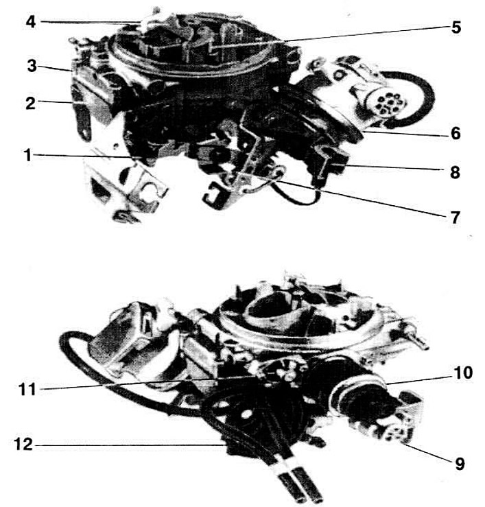
External appearance of the 2BE carburetor:
1 — throttle body; 2 - float chambers; 3 - carburetor cover; 4 - air damper; 5 — idle air jet needle; 6 — 1st chamber throttle valve servo drive; 7 - idle switch; 8 — idle speed switch connector; 9 — 1st chamber throttle potentiometer; 10 — air damper servo drive; 11 — shut-off (blocking) 2nd chamber valve; 12 — pneumatic drive of the 2nd chamber.
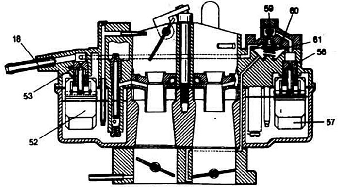
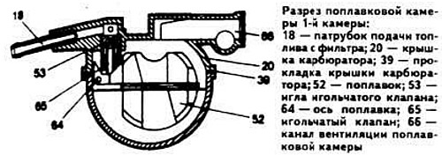
Sectional view of the 2BE carburetor:
18 — fuel supply pipe with filter; 52 — float of the 1st chamber float chamber; 53 - needle valve of the 1st chamber; 56 - needle valve of the 2nd chamber; 57 — float of the 2nd chamber float chamber; 59 - 2nd chamber shut-off valve; 60 — diaphragm; 61 — 2nd chamber shut-off valve spring.
[The original text of the article is available on the resource: bmwman]
This article is available at russian, bulgarian, belarusian, ukrainian, serbian, croatian, romanian, polish, slovak, hungarian
Article verified: Polikarpov Saveliy
Share information:
Previous articles
БМВ E12: Ecotronic power supply system
Next articles
Similar articles on other types of BMW cars:
Removal and installation of the Solex DIDTA 32/32 carburetor BMW 3 Series E21 (1975-1983)
Carburetor fault diagnostics BMW 3 Series E30 (1982-1994)
General description of the car BMW 7 Series E32 (1986-1994)
Fuses — general description BMW X3 E83 (2003-2010)
Cylinder Block — Design Description BMW X5 E53 (1999-2006)
Link in different formats to this page
Visitor comments
No comments yet
- General information
- Governing bodies
- Manual
- Maintenance
- Power unit
- Engine repair
- Lubrication system
- Cooling system
- Ignition system
- Supply system
- Injection system (gasoline)
- Injection system (diesel)
- Exhaust system
- Transmission
- Clutch
- Car gearbox
- Front axle
- Rear axle
- Chassis
- Steering
- Brake system
- Wheels and tires
- Body
- Interior
- Exterior
- Heating system
- Electrical equipment
- Equipment and devices
- Power devices
- Windscreen wipers
- Electrical circuits
- General information
- Manual
- Maintenance
- Power unit
- Engine repair
- Ignition system
- Engine lubrication system
- Cooling system
- Fuel system (gasoline)
- Fuel system (diesel)
- Exhaust system
- Transmission
- Clutch
- Car gearbox
- Chassis
- Front and rear suspension
- Steering
- Brake system
- Body
- Exterior
- Interior
- Electrical equipment
- Heating system
- Equipment and devices
- Power devices
- Electrical circuits
- General information
- Manual
- Maintenance
- Power unit
- Engine in a car
- Engine overhaul
- Cooling system
- Supply system
- Ignition system
- Control system
- Transmission
- Clutch
- Manual gearbox
- Automatic gearbox
- Transmission line
- Chassis
- Steering
- Front suspension
- Rear suspension
- Brake system
- Body
- Body elements
- Car care and painting
- Electrical equipment
- Heater and air conditioner
- Equipment and devices
- Starter and generator
- Electrical circuits
- General information
- Operation and maintenance
- Specifications
- Power unit
- Engine repair
- Cooling and lubrication system
- Supply system
- Ecotronic power supply system
- Fuel injection system
- Ignition system
- Transmission
- Clutch
- Gearbox BMW 242/4
- Gearbox Getrag 262/8
- Gearbox Getrag 265/6
- Automatic gearbox
- Cardan gear
- Rear axle
- Chassis
- Steering
- Front suspension
- Rear suspension
- Brake system
- Electrical equipment
- Equipment and devices
- Electrical circuits